An emerging capability in computer simulation makes it possible to model core-gas pressures that result from thermal degradation of resin-based binders in sand cores. The model, part of the FLOW-3D casting simulation software, is being developed at Flow Science Inc.1,2 and is designed to help the foundry engineer evaluate core-venting strategies for a variety of mold-filling conditions.
The core-gas model incorporates a realistic binder decomposition gas source and reports core-gas pressures, possible surface locations of binder gas loss into the metal, binder degradation zone evolution and binder gas flow fields. These diagnostics can be computed concurrently with filling and freezing patterns. Because the chemistry of thermal binder decomposition is complex, the Flow Science team has collaborated with experimental groups at University of Alabama in Birmingham3 and at AlchemCast LLC4 to ensure reasonable accuracy of the computed binder loss and gas generation rates for resin-based binders.
The core-gas model
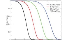
The breakdown of the sand binders begins at the core surface, which heats into the binder decomposition range shortly after immersion into metal. The existing data indicates that the decomposition range of polyurethane based binders is roughly between 440° and 800°F (see Fig.1). The computational model assumes the worst case scenario of complete binder mass conversion into gas and the gas is taken to have a fixed composition. The gas generated in the core flows towards the vents with the associated pressure loss. Since the vents typically remain at much lower temperatures than the regions where the binder is gasifying, significant thermal contraction of the binder gas during flow is expected and the product gas is treated as compressible. Furthermore, since the main volatile species (carbon monoxide, carbon dioxide, hydrogen, methane) flow at temperatures and pressures well above the component condensation points, the product gas is treated as ideal. Water vapor is clearly an exception and is not considered in the model.
The key flow parameters for prediction of core-gas pressures are the Darcy’s sand gas permeability and the gas constant of the mixture. At 40% porosity, sand permeability is approximately 10-7in2, which amounts to about a 40 in/sec flow at a 1 psi/in pressure gradient. The gas constant is deduced from the calibration measurements. In these, a small cylindrical core specimen is immersed in metal at a depth where the core is sealed (see Fig.2, right panel.) The product binder gas is collected through the open top face in an apparatus that is either a pressure measurement device, or a fluid displacement device. In both cases the rate of evolved gas volume is reported vs. time. The total collected gas volume and the initial binder mass can be used to compute the gas constant which is approximately 350 J/kg/K for a polyurethane cold box (PUCB) binder. This corresponds to the molar mass of 23 g/mol and the collected product gas is somewhat lighter than air.
The left panel of Fig. 2 shows the measured volumetric gas rate from one calibration PUCB core, 1.125 in. diam. and 2 in. long, immersed in iron at 2,600°F. The core is printed into a steel holder to 0.5 in. Also shown is the result of a computation with the core-gas model. The agreement is good for both the peak time and the peak rate. The overall core degradation time is also captured well and is about a minute and a half.
The shape of the volumetric rate curve can be related to the underlying time-dependent geometry of the binder degradation zone and the corresponding local inzone heating rate. The peak corresponds to the degradation of the core surface where the heating rates are highest and surface of the decomposition zone is just the core surface. As the heat penetrates the core, the heating rates drop, the zone surface shrinks in size, and there is a concurrent increase in the zone thickness which is responsible for the simulated plateau in the evolved gas rate. A smaller plateau is also present in the data around 20 seconds after immersion. The shape of the degradation zone at 30 seconds is plotted in the right panel of Fig. 2. The color variable is the rate of binder density loss. In the region behind the zone, adjacent to the core surface, the binder has completely degraded. Ahead of the decomposition zone the binder is still intact.
An important feature of the core-gas model is its ability to predict amounts and core surface locations where possible gas blow takes place. During the computation the surface gas pressure is compared with pressures in the adjacent mold region and reset to the local metal pressure if the gas pressure is in excess. At the same time the gas flux at this location is recorded. A given core design can be evaluated by considering locations and amounts of gas blow, or by comparing the total gas generated with the total core-gas blow into the metal.
In the early calibration experiments the length of the calibration core in iron and steel immersions was 4 in. There was evidence of gas blow into the metal since the total collected gas from a core half the size was not much smaller. The model correctly predicted gas blow in the longer cores immersed in steel. Fig. 3 shows the gas and metal pressures and the surface blow locations and fluxes . As expected the gas escapes along the upper portion of the core where the metallostatic head is smaller. Simulations also showed that additional 2-3 inches of depth were sufficient to seal the core. However some amount of blow was unavoidable due to the speed at which the gas pressure built up. The cores are manually lowered into a crucible and some gas will escape into metal during the immersion.
Ongoing development, validations
To date the model has been used successfully to study venting strategies in an engine block water jacket core. The simulation results were in good agreement with the foundry tests. In these tests the mold was bottom filled with aluminum and was left open for observation of possible gas bubbles at the metal surface. The core-gas model correctly predicted the timing and the amount of blow for vented and nonvented jacket cores. Complete details of this validation study will be presented at the upcoming MCWASP XII conference1.
More recently the model has been used to compute possible blow locations from an oil core, which presents significant challenges for the caster. The oil core has a high surface area, a small casting modulus, and a typical orientation is horizontal resulting in long venting paths. The model can be used in this case to size the distance between the vents to suppress the coregas blow, or to evaluate the amount and location of blow in designs with less than adequate venting. Given a 2- to 3-second delay between the exposure of the core surface to aluminum and significant decomposition of the binder at the surface, a designer can also establish an adequate fill rate to provide enough metal head to minimize core-gas blow.
The ongoing work at Flow Science is focused on model validation for iron and steel castings where the peak gas rates are higher and time to peak is shorter. Work is also focused on top poured medium-tohigh production rate castings with multiple cores where mold filling patterns are possibly complex and the dominant core-gas venting path can be changing several times throughout the fill.
The developers welcome comments and will appreciate any test cases the readers might want to share with the Flow Science team.
References
1. Starobin A., Hirt C.W., Goettsch D., ibid, “A Model for Binder Gas Generation and Transport in Sand Cores and Molds,” MCWASP XII, 2009, in press
2. Flow Science Inc., Santa Fe, NM. www.flow3d.com, 2008
3. Winardi L., Littleton H., Bates C.E. “Variables Affecting Gas-Evolution Rates from Cores in Contact with Aluminum,” FM&T, August 2007
4. AlchemCast LLC, Pelham, AL www.alchemcast.com


