
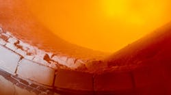


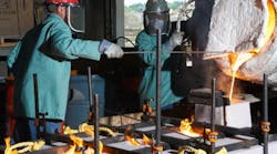


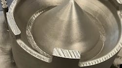

Rexroth Guss is a metalcasting subsidiary of Bosch Rexroth AG. With a foundry in Lohr am Main, Germany, it produces gray and ductile iron castings for hydraulic drive components. These are complex, “core-intensive” structures with many free-form surfaces that are designed in 3D before prototypes or test castings are produced.

In addition to the castings for hydraulic components, Rexroth Guss supplies parts for the parent group’s general machine construction worldwide. It maintains a comprehensive quality-control system that covers destructive and non-destructive material testing, as well as metallurgical analysis.
The transition from 2D to 3D design several years ago prompted Rexroth’s quality-control department to look for an appropriate measuring solution. “The requirements for quality assurance have increased with 3D technologies,” according to Rexroth Guss manager for Product Quality Management Frank Mill.
“Earlier,” he recalls, “all major dimensions could be taken from a 2D drawing for tactile measurement, which is no longer the case. Modern 3D drawings include little in the way of explicit dimensions. The curves of the free-form surfaces are almost impossible to verify using traditional tactile-measurement techniques.” Recognizing that they must adopt 3D scanning technology, quality control technicians
at Rexroth Guss were persuaded to adopt a low-cost non-contact scanner from the Wenzel Group. The Shapetracer high-precision line scanner was developed together with a software product for evaluating measurement results, the Pointmaster. (The software was developed by Wenzel Knotenpunkt, which the group acquired last year.) Shapetracer is a compact unit that can be connected to the Renishaw PH6M or PH10M probe head via the Renishaw Autojoint connection. As such, it be adapted to nearly all coordinate measuring machine models. In conjunction with the PH10M rotary swivel head, five-axis measurement is available.
Rexroth Guss’ quality team realized from the start that the new laser scanner should be used on a coordinate measuring machine with a stable support table, not just on a mobile measuring arm. “Our future intention is to fully automate the measurement of several workpieces or die plates with multiple molding stations,” explains Frank Mill, “and that is only possible on a large stationary measuring machine.”
| CMM TECHNICAl DATA | |
| Dimensions | 100 68 58 mm |
| Working clearance | 40 mm |
| Scan width | 35 mm |
| Scan depth | 60 mm |
| Scan capacity | 48,000 points/sec |
| Measurement accuracy | > 20 μm |
| Because designed to be compact, the Shapetracer can be mounted easily in sensor changer systems — meaning that any conventional measurement machine can be upgraded to become a multi-sensor machine. | |
Lately, a horizontal arm machine (Type RS 1012) has been introduced by Wenzel, so customers now have a single-source supply for a complete CMM installation. In addition, a sensor changer was installed to make switching from tactile sensors to the laser head a fully automatic function. Because the Shapetracer is cabled via the Renishaw Multiwire connection, storing it together with other measurement heads is simple.
Not all of the functions of the Pointmaster software have been deployed at Rexroth Guss. “Comparisons of target data to actual data have been at the top of our wish list as we get started in the new measurement technology,” explains measurement technician Achim Werthmann, who is well versed in operating the scanner solution. “One of our next priorities will be surface reconstruction.”
The workflow for target-to-actual comparisons that Werthmann describes is:
• Scanning the workpiece, with the operator supported by the Pointmaster kinematics module as the software controls the measuring process. The measuring machine can be mapped, completely and virtually, so that simulations of the measuring process are also possible.
• A point cloud is generated from the scan data. From that data;
• A polygon model with a homogenous surface is computed by triangulation. Finally,
• The polygon model is converted into a CAD model in IGES format. Rexroth Guss quality technicians receive the CAD data, also in IGES format, from the design department; and
• The target data and actual data are aligned and compared with the software.
Pointmaster highlights the differences between the two models in “pseudocolors”; the dimensional variances can be discretionally selected and marked by flags. All dimensions are listed and contrasted in the evaluation protocol. “As this involves complex workflows, the measurement technician must fully master the individual process steps,” Frank Mill emphasizes. “For this reason it was important to us to build up the relevant expertise inside our company.”

During the transition phase to 3D an external measurement service provider was appointed for a while. “Any outsourcing of such work involves a lot of uncertainties as well as time loss,” Mill adds.
This is particularly relevant for components with complex inner workings. Such parts must be dissected in order to simulate both the external and internal contours. “This software means it is not a problem to construct a model from the component scanned in different directions,” Werthmann explains. The system provides a series of functions, for aligning the components and for manufacturing homogeneous contour transitions in order to remove any cut surfaces, and to add consecutively scanned areas.
Wenzel Knotenpunkt developed the function for assembling the contours so that it does not rely on mathematical tricks. It always uses real data, so, an especially precise scanner is a prerequisite, and the level of accuracy satisfies Werthmann. “We don’t know of any comparable systems that offer such high precision,” he points out. After the CAD model has been generated the finest surface structures become visible. For example, imprinted text appears distinctly and clearly legible on the display screen.
In dimensional measurement, “accurate” may mean something different in theory than it does in practice. The developers of the Shapetracer line scanner put a great emphasis on practice-oriented data.
“Shapetracer provides a measurement accuracy of better than 20 μm,” explains Ralf Jaumann, managing director of Wenzel Knotenpunkt. “This value is not a theoretical specification based on specified accepted boundary conditions. This value was proven metrological with the aid of verified calibration figures. It is essential to be aware that, apart from the camera resolution, the accuracy of a laser sensor is primarily dependent on the depth of scanning.
“The greater the scanning depth, the more inaccurate the result will be. The Shapetracer was therefore optimized for a scanning depth of 60 mm in order to obtain the specified accuracy,” adds Jaumann.