


The biggest difference between iron and other alloys is graphite expansion during solidification. This is significant because in most situations the casting becomes “self-feeding” after the onset of expansion, and no further feeding is required. Once expansion begins, a feeding system should control the expansion pressure to ensure that the casting is self-feeding from that point forward. With shrinking alloys, feed metal must be supplied during the entire solidification time.
Consider the example of a cast ductile iron control arm, shown in Figure 1. The foundry originally approached the feeding design for this iron casting by placing two symmetrical feeders, as shown in Figure 2.
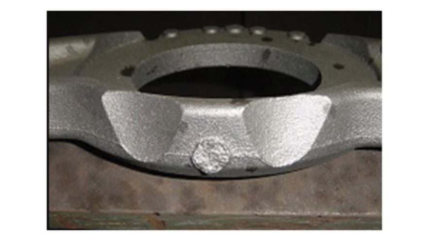
During initial production of this casting, porosity occurred consistently at one feeder contact, as shown in Figure 3. The porosity does not always show at the same contact, but on all castings one contact showed porosity and the other did not. No acceptable castings were produced with this pattern design.
Next, this casting was analyzed using the approach described previously to determine feeding requirements. First, an unrigged simulation was performed. Then, the simulation data was converted to Modulus data so that feeding calculations could be performed.
Figure 4 shows a plot of the areas of highest Modulus in the casting. From this plot, the foundry engineer might be tempted to conclude that the original feeder design was correct, as there are two areas of high Modulus value in the casting and these are adjacent to the feeder contacts in the original design.