


There is one segment of metalcasting suppliers who can be confident about their prospects for equipment sales and service contracts, even in the current economy. Builders and suppliers of robotic automation equipment can promise to lower a foundry’s or diecaster’s employment costs and raise production efficiency, simply because of the availability and reliability that robots offer for a range of metalcasting tasks: core and mold handling, ladle transport furnace tending, pouring, handling of finished castings, as well as automated cleaning and machining of products. It may not be polite to emphasize these potential cost-savings, but they’re real.
Making the case
The robotics world knows this well, and metalcasters are growing more aware of the expanding applications for automation systems in their operations. RobotWorx doesn’t build robots; it integrates automation work cells into industrial operations, supplying a variety of models and parts from different manufacturers. It identifies a series of reasons for metalcasters to incorporate robotic work cells:
• Robot designs offer increasingly robust payload capabilities and wide work envelopes allow robots to lift heavy and outsized loads (think of mold boxes, or engine blocks), easily, repetitively, and reliably.
• Robots endure the intense heat, airborne dust, and dangerous zones of foundries, without danger to their “health.” While human workers risk burns, exhaustion, repetitive motion injuries, or respiratory damage, robots are immune to such concerns. And, RobotWorx points out, “foundry robots are required to have an industrial protection rating (IP 55). They can endure the hazards with ease and work without fatigue. Even when the heat is extremely intense, robotic EOAT can be safeguarded.”
• Robots reduce the risk of dropped or damaged parts, and fewer accidents reduce financial risk. Concerns about training and employee retention are minimized, because there is virtually no “worker” turnover, and automation technology makes it fast and simple to program robots. Productivity — output (product value) divided by input (production costs) — grows because robots “employment costs” are comparatively low, and stable, and robots don’t take work breaks or vacations.
• Robotic automation delivers high repeatability to metalcasting process, with each motion carefully and accurately programmed. For precision finishing of high-quality parts, automation is exceptionally reliable.
• Robots make operations more flexible, because robots can perform various tasks (sampling, deburring, grinding/ sanding, pick-and-place material handling, etc.) Automatic tool changing makes it possible for a robot to switch tasks, which in some operations will simplify and speed operations.
Tough enough
Robotics designers have been doing their part to enhance their product offerings for metalcasting performance. FANUC Robotics America last year introduced the M-710iC/50 SE FoundryPRO robot, “designed for super harsh environments,” rated to IP67. The entire structure is specially epoxy-coated, and the wrist unit is protected against high-pressure washing. Also, the base of the robot purges air to avoid vapor entrance.
“The M-710iC/50 SE sets the benchmark for robots working in the super harsh environments of diecasting and foundry facilities,” according to FANUC Robotics product manager Virgil Wilson. “In addition to the protective epoxy and air purge, we’ve incorporated coated bolts, and double oil seals at the joints, making this a truly waterproof robot.”
The robot has a six-axis operating range, a reach of 1,360 to 3,110 mm (53.5-122 in.), and handles payloads from 20-70 kg. It can be mounted from a floor, ceiling, angle, or wall, so operations can adopt it in virtually any work cell.
“This is an exciting robot based on its capabilities and flexibility,” Wilson says. “It’s rated ‘best in class’ for speed, and has one of the largest work envelopes in its class. In addition, its compact size and ability to flip over and work behind itself maximizes flexibility for work-cell design, and saves valuable floor space.”
KUKA Robotics last year introduced a grandscale, heavy-duty, six-axis robot: the KR Titan 1000 is a floor-mounted design for payloads up to 1,000 kg (2,200 lb), targeting foundries and automotive plants, among others. It has a supplementary load capability of 50 kg (110 lb), and a maximum reach of 3,202 mm (10.5 ft.) It’s repeatability is pegged at <±0.2 mm. KUKA points out that it outfits the foundry version of this robot with abrasion- and heat-resistant paint, special seals, and the wrist device carries a IP 67 rating.
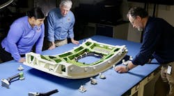
Vulcan Engineering does not develop robotic devices, but it designs foundry operations. Robots of all sizes and functions find a place in their installations. Recently, a manufacturer of steel weighing up to 3,000 lb. (and larger) asked Vulcan to improve its heavy grinding operation. Vulcan installed a robotic cell, centered on a foundry-duty ABB IRB 7600 robot, and software and measurement technologies to handle the dimensional variations inherent in the customer’s grinding process.
The cell has a heavy-duty load/unload turntable; a servo-driven, two-axis part manipulator on each side of the turntable; the ABB device (); a 100-hp hydraulic grinder; laser measuring for part calibration; wheel measurement and dressing system; and Vulcan’s TruPath 3D software for robot-path “tuning.”
Grinding of large and/or heavy parts has always been formidable, as is moving them between steps and manipulating them through the processes. Grinding them typically involves removing large quantities of metal, but due to manual constraints the horsepower of the grinding tool often is limited to what an operator can readily handle. The combination of difficult handling with severe power and pressure limitations results in inefficient, labor-intensive, time-intensive operations.
Another significant problem is partto- part and run-to-run dimensional variations inherent in most large-size molding operations, as well as customers’ standards for product and consistency.
Vulcan used robotics as the core of an efficient and ergonomically sound process. The robotic cell is designed to grind large, thick flash from oversized steel parts, which requires a high-powered hydraulic grinder and resin-bonded abrasive wheels. (With other materials and processes, electric grinders and “super abrasive” wheels may be used.)
Today’s high-payload capabilities and consistent performance under load make robots capable of carrying very powerful tools. Vulcan’s finishing cell uses a hydraulic grinder powered by a remotemounted hydrostatic unit, with a 100-HP (73-kW) motor. The six-axis, foundryduty robot, with a capacity of 400-kg (880 lb), is strong enough to apply the pressure needed to utilize the grinder horsepower fully, as well as the abrasive itself.
| Safety Priorities for Robot Tool-Exchange Systems Applied Robotics designs “end-of-arm-tooling” (EOAT), including collision sensors, grippers, rotary actuators, and tool changers. It says the first safety measure to prevent tool drops to create a safe zone within the robot programming, to ensure that the tool will only uncouple in areas determined to be safe, that is, where no harm will come to operators or equipment if a tool is dropped. Having a work-cell zone defined in the robot controller, prohibits a tool from uncoupling if the robot is not within the zone. Coupling/uncoupling is the most critical function to manage, and specific considerations include sensors and pneumatic interlock devices, and set-up and programming techniques. The latter includes “program touch-up or refinement, maintenance, repair, testing, set up or adjustment.” Controlling the actuation valve to ensure proper coupling/ uncoupling is also important to safety. Electrical interlock logic or pneumatic interlock logic are recommended, and a pneumatic safety switch is an additional safety measure. High voltage is a significant safety concern for toolexchange systems. If the tool changer is not adequately equipped to handle high current levels, and degrades over time, a malfunction and subsequent tool failure may occur. Measures for addressing this include selecting durable materials (e.g., fiberglass epoxy laminate FR4) to provide a dielectric constant that will prevent current leakage through the tool-changer housing, eliminating sensor shortages, motors burning, and electrocution. Workers in the vicinity of the work cell must not be exposed to hazards, so the robot contacts must be safe to touch when the tool changer is not engaged. Lastly, newer “high dynamic” robots (eg., ABB’s IRB 6600 and 7600 series, and KUKA’s KRC series) are designed to help reduce cycle time and generate greater productivity; they generate high dynamic forces, particularly at an emergency stop. So, all tool-exchange systems must meet the strict requirements of these devices with direct mounting and robust locking mechanisms. Tool-changers should be engineered for the “worst case” robot capability, not the actual loads generated within a specific tool. For example, ABB’s IRB 7600 can generate 14.0 KNm at the tool-mounting surface. These forces must be well below a tool changer’s failure point, so that it has inherent strength greater than moments or torques generated by the robot, even under the most adverse conditions. |