Understand the Effects of Zinc Penetration on Induction Furnace Linings … and How to Compensate for It
To improve corrosion resistance in automotive applications, a zinc coating is applied to steel sheet. While effective for its intended purpose, the zinc coating leads to problems when zinc coated scrap material is recycled as a base material for iron castings in foundries.
The ironmaking process requires some adjustments to minimize zinc contamination of the molten iron. For example, it helps to charge the zinc-coated steel scrap early in the melt cycle, allowing more time for the zinc to evaporate out of the melt. An extended melt cycle also may be necessary, to get the zinc concentration down to acceptable levels.
A significant problem with this approach is that the zinc also affects the refractory lining material, requiring some changes to the sintering procedure. It has been found that using zinc-free material for the sinter heat helps to reduce the amount of zinc penetration into the lining.
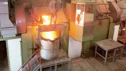
Zinc has a low melting point of 407° C and a very low vaporization temperature of 920° C. When zinc vapor is exposed to air, zinc oxide is immediately formed. As zinc-coated scrap is melted, the zinc is dissolved into the melt. At the free surface on the top of the melt the zinc vapor is exposed to air, where it oxidizes and combines with the slag layer that is removed before tapping the furnace. Some of the vapor is oxidized into zinc oxide dust, and carried away by the furnace exhaust system.
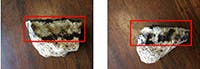
At the hot face of the lining the zinc vapor diffuses into the lining material. A matrix of metallic zinc and refractory granules is formed, which at the high temperature becomes highly conductive. Power is electrically induced into this area during operation, changing the electrical characteristics of the furnace. The furnace behaves as if its lining is worn more than physical measurements would indicate. Some examples of refractory material contaminated by zinc are shown in Figure 1.
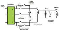
In the case of a line-frequency furnace, the melting vessel operates at a voltage determined by a range of fixed voltage taps (see Figure 2). Several taps are allowed above and below the nominal tap at which rated power is achieved with a new lining.
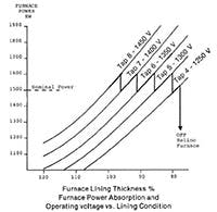
As the lining wears, the electrical impedance of the furnace decreases while at the same time the induced power increases, necessitating changing taps to lower the voltage over the course of the lining campaign. At the end of the lining campaign, where the average lining thickness is around 70% of a new lining, the furnace reaches rated power at the lowest constant power tap (Fig. 3). At that point, it is necessary to change the lining. As the lining wears, capacitors are switched in automatically to compensate the power factor of the furnace coil close to unity.
The presence of zinc in the lining material can cause the furnace to look electrically as if the lining is worn about 0.5- to 1-inch more than its measured thickness. With a line frequency furnace, the limited range of tap voltages can be exhausted prematurely, resulting in very short lining campaigns.
For an example, let’s consider a six-ton furnace that is rated for nominal power of 1500 kW at 1450 V, 60 Hz, with a new lining. This furnace has five constant power taps ranging from 1,250 to 1,450 V. In normal operation without zinc penetration, the furnace lining lasts four weeks as the taps are reduced until the furnace reaches the fourth tap at the end of the lining campaign.
With zinc penetration, the furnace reaches rated power a fifth tap within the first week, and then the furnace lining must be changed.
One possible solution to counteract this phenomenon is to decrease the lining form diameter by 1 inch. The initial power draw then will be limited to 1,350 kW, with a new lining at 1,450 V. By the end of the second week, the power gradually increases back to 1,500 kW. In the third and fourth weeks the furnace is tapped down as the lining wears.
Using this approach, the full lining campaign duration can be achieved. The tradeoff is that the power may be reduced somewhat during the first week. The production rate may be correspondingly reduced for that week.
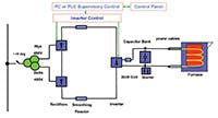
With a medium-frequency furnace system (see Figure 4), there is usually a much wider range over which the voltage can vary while maintaining constant power, so the impact of the zinc may not be very noticeable, beyond a shift in the range of frequency and voltage variation compared to operation with a zinc free lining.
With a medium frequency-furnace system, voltage and frequency changes are proportional to lining wear (see Figure 5.)
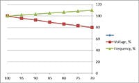
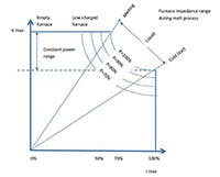
Zinc penetration reduces the electrical impedance of the furnace, causing the voltage to drop while the frequency rises. Providing that the voltage and frequency remain within the normal constant-power operating range of the power converter (see Figure 6), rated power can be maintained throughout the lining campaign.
To compensate for zinc penetration, the following steps can be taken to mitigate its effects:
1. When sintering a new lining, use only zinc-free scrap. This allows a zinc-free glassy hot face to form during the sinter heat. The sintered hot face will resist the penetration of zinc vapor.
2. When cold starting, the same precaution applies. Using only zinc-free scrap will prevent zinc vapor from entering the cracks that formed in the lining during its last cool-down.
3. Special refractory washes can be applied to the outer surface of the lining form that will help to seal the hot face of the lining, resisting zinc vapor penetration. Zinc-free scrap still should be used for the sinter heat.
4. On some systems, the thickness of the lining can be increased to compensate for the electrical effects caused by the zinc penetration. Care must be taken to ensure that the added thickness of the lining does not push the operation of the system outside of its constant power operating range, affecting production rates near the beginning of the lining campaign.
Daniel Green, PhD, is the technical director for ABP Induction, a developer and integrator of induction-related equipment and services for foundries and other industrial heating operations. Contact him at [email protected], or visit www.abpinduction.com