


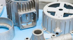
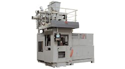

Foundries use automated matchplate molding machines to form sand molds, and those molds are subsequently filled with molten metal material, cooled and then broken apart to release metal castings. When Hunter Foundry Machinery Corporation introduced its HLM Series machines to the global casting market, with the first machine delivered to Progressive Foundry Inc., Perry, IA, it signified a proprietary new concept in automated matchplate molding technology.
“For the first time in our industry, the new HLM Series combines and integrates magnetically coupled rodless cylinders and linear bearings for movements of the squeeze platen, cope flask, sand measuring hopper and other components on the machine,” said the system developer and patent-holder, Hunter Foundry Machinery president and CEO Bill Hunter.

Previously, cam followers, wheels, tracks, rails and other mechanical components subject to wear and degradation were used for these machine motion functions. In contrast, Hunter explained, “The HLM offers sealed linear motion slides and magnetic rodless cylinders to replace these older components, providing smoother, quieter and more energy efficient operation with less maintenance and greater machine stability.”
More improvements incorporated to the design include a support frame, a cope flask for making cope molds, a drag flask for making drag molds, and a pattern plate adapted to be positioned between the cope flask and the drag flask, and typically fixed to the drag flask, for forming patterns in the cope and drag molds.
HLM Series machines include a squeeze station with a squeeze head that’s received at an open end of the cope flask. Expandable/retractable actuators, such as pneumatic or hydraulic pistons, are mounted between the cope and drag flask and the support frame to drive the cope and drag flask relative to the squeeze head.
A drag flask filling station is horizontally adjacent to the squeeze station. The flask is cyclically shifted back and forth between the
The support frame has cylindrical legs at the squeeze station, and the cope flask is movably mounted on each of these frame legs by a cylindrical linear-motion slide.
Similarly, the squeeze station includes a platen table assembly driven by a hydraulic actuator. During operation, the platen table is elevated and carries a drag flask, pattern plate, and mold in contact with a bottom surface of the cope flask and mold. As such, the drag flask, pattern plate, and cope flask are driven toward the squeeze head, and that is movably mounted on each of the cylindrical frame legs by a cylindrical linear-motion slide.
Each cylindrical linear-motion slide can include a cylindrical housing enclosing a cylindrical bearing that extends around an outer circumference of the corresponding vertical frame leg.
The Shifting Hopper Car
The hopper car shifts horizontally relative to the support frame via one or more linear-motion slides, between the squeeze station for filling the cope flask with sand and the drag flask filling station for filling the drag flask with sand. Each linear-motion slide can include a cylindrical shaft mounted on the support frame or hopper car, and a linear-motion bearing slidably mounted about the cylindrical shaft. The linear-motion bearing is disposed in a bearing housing that is connected to the hopper car or support frame. The linear-motion slide(s) may include a compensation mechanism that allows displacement caused by the movement of the squeeze head to contact upper frame stops of the compensation mechanism during the mold making operation.
The molding machine may incorporate a rotary cradle in the filling station that receives and holds the drag flask during filling. A
Each rodless cylinder is pivotally mounted to a board feeder head plate of the board feeder. The board feeder can include a board feeder head plate pivotally mounted on a carriage of the rodless cylinder, such as by a bearing between the board feeder head plate and the carriage. The carriage can be magnetically coupled to a piston that moves within a corresponding cylinder of the rodless cylinder.
Several versions of the design include a spray head (such as for applying a release agent to the pattern plate) in the filling station, and a spray vapor evacuation device adjacent to the rotary cradle or the spray head. The spray head can include a spray nozzle oriented toward the rotary cradle for spraying the release agent on the pattern plate as it comes into the rotary cradle, and the evacuation device is desirably disposed in or around a spray area between the spray head and the rotary cradle.
The evacuation device can include a tube connected to a vacuum source, such as an inline vacuum pump in combination with the evacuation tube. A separation device including at least one of a cyclonic separator or a water separator can also be used in combination with the tube to separate some or all of the captured release agent vapor from the air in the tube.
One design variation, the evacuation device includes a tube end in combination with a gap formed between an inner plate of the drag flask and the pattern plate, such as for collecting spray vapors near the point of intended contact with the pattern plate.
“We have incorporated this modern linear motion design because we believe it will have a significant, positive and immediate impact upon the foundry world,” Bill Hunter concluded.