


It is generally accepted that a low-velocity pneumatic sand-conveying systems designed with low air volume and high air pressure outperform high-velocity systems with high air volume and low air pressure, every time.
A low-velocity pneumatic sand-conveying system can be designed with minimal moving parts for semi-continuous transfer of free flowing, dry sand. The blow tank transfers the sand in small batches from a feed bin at atmospheric pressure into the continuously pressurized pipeline. Short fill times for the blow tank and constant air injection into the pipeline are used to generate an almost continuous conveying process.
A low-velocity sand-conveying system consists of a bulk sand surge bin; the blow tank assembly with controls; the standard Schedule 40 steel pipeline; one or more sand receiving bins with level probes and diverter pinch valves; the dust-collection system for the receiving bin(s); and a source of compressed air. During sand transfer the pipeline remains full of sand at all times, no additional air (boosters) is injected along the pipeline, and no air purge is required at the end of a conveying cycle, which allows the system to operate with considerably less compressed air than most conventional pneumatic conveying systems found in a foundry.
Preventive maintenance or the need for preventive maintenance starts with full disclosure of the pneumatic conveying application at the design stage. This includes specifications for the sand to be transferred, the tonnage required, utilities (power and compressed air) available, the source of the compressed air (main plant air supply or dedicated job sized compressor), location of the blow tank assembly, layout and length of pipe run, pipeline supports, as well as location of receiving bin(s) and dust collector. By having the basic data available the system can be designed for optimal operation and parameters established for monitoring system performance.
After the system has been installed and is ready to operate it is good practice to perform an air-pressure test by sealing all openings and pressurizing the piping system to 125% of operating pressure. The system should be able to hold the test pressure, as indicated by a pressure gage, for at least one hour. A reduction in pressure during this time indicates a leak that must be found and eliminated. Many times flanged connections have not been tightened correctly during installation or welds are not airtight and must be repaired. Since a low-velocity system uses less air than conventional high-velocity systems even small air leaks affect performance.
After a successful pressure test and during system start-up, after the proper adjustments to air flow and air pressure have been made and expected performance is achieved, it is recommended to measure and record compressed-air pressure, compressed-air flow rate, blow-tank cycle time, and tonnage delivered.
Because operating usage of any new pipeline will scour and smooth the interior surfaces to some degree, causing the system to become "faster", it is recommended to repeat the readings and readjust settings, if necessary, to obtain design conditions. To promote consistent system operation and to guide future adjustments a simple table or data sheet should be developed to record the collected data, together with the date of the test, and kept for easy reference. One important item, normally overlooked or ignored in the original system test, is the analysis of the sand to be conveyed. Particle-size analysis and bulk density, at a minimum, should be recorded initially because sand of different characteristics have a definite effect on system performance.
Once the conveying system has been placed into service and operating parameters have been collected and recorded the system should perform at expected levels for extended periods of time without problems. To prevent unexpected disturbances, however, it is strongly recommended to perform routine maintenance of the major system components, such as compressed-air supply, blow tank assembly, piping run, diverter pinch valves, receiving bin(s) and dust collector as outlined here.
Sand surge feed bin. The sand feed bin, located above the blow tank, arranged for sand flow into the blow tank by gravity, should be checked occasionally for unobstructed sand flow. Depending on how the bin is filled (either bulk bags, bulk truck etc., or by open top) any debris collected on the inlet screen should be removed.
Compressed-air supply. Compressed air that blows the sand through the pipeline must be free of moisture, oil, or other impurities. Not only does condensed moisture in the air affect the sand flow properties but also the quality of the cores being made from the sand. To achieve the desired dry-air conditions a properly sized air drier and filtration system should be used and frequently checked for proper performance.
Recommendations of the compressor manufacturer should be followed for mechanical checks, such as oil level, drive train etc., periodic checks of the intake filter condition, pressure gage, pressure differential switches, temperature switches, and overload relief valves. Depending on quality of the intake air the inlet filter needs to be inspected and cleaned or replaced at certain intervals. Pressure gages should be checked occasionally against test gages for accuracy and should be protected from pulsations by snubbers to dampen any surges.
If installed, pressure differential switches can protect the compressor against excessive overpressure and should be checked routinely at certain intervals. Temperature switches set to signal when exit air temperature rises above a safe level should be checked for proper operation and response time.
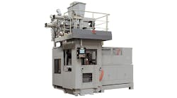
Blow tank assembly. The operation of the blow tank or pressure vessel assembly is controlled by a PLC, normally using a single non-contact proximity switch to indicate the position of the sand outlet valve and a bank of solenoid air valves. Cycle times are set during start-up and monitored automatically by the PLC. A built-in cycle counter should be used to schedule routine maintenance for the various components as listed in the supplier’s maintenance manual.
After a certain cycle count is reached the sand inlet valve seal needs to be checked and replaced if wear is excessive. At the same time, all components in contact with the sand during operation need to be checked for wear, and replaced if necessary. Also, check for the correct seating of any proximity switches or level probes and inspect external wiring for visible damage. While inspecting the sand inlet valve seal, the inlet valve cone also should be checked for patterns of abnormal wear around the periphery, which would indicate a damaged seal.
Safety Note. Prior to any inspection on the blow tank assembly, all air pressure to the unit must be turned off, locked out and drained, and the actual pressure vessel must be vented by actuating the manual bypass control on the inlet air solenoid valve. Inspect the pressure gage and air flowmeter in the compressed-air supply line making sure that both instruments are in good working order.
Pipe run. Visually inspect the pipe run for possible leaks or external damage from operating equipment in the area. The pipe run must be rigidly supported over the entire length and pipe supports need to remain firmly anchored to support structures or foundations to absorb dynamic and static loads during operation, and loose connections must be prevented.
Diverter pinch valves. Diverter pinch valves, used for multiple receiving bins, should be checked for proper closing and opening by observing the pressure gages normally installed in the air supply lines to the valves. If pressure drops are observed during the test, it’s likely the sleeve or bladder of the valve is worn and must be replaced.
Receiving bin(s). Each receiving bin should be equipped with level probes indicating sand presence in the bin. Signals from the level probes normally control the operation of the blow tank assembly and, for multiple bins, control the opening and closing of the pinch valves to adjacent bins. Since the level probes have solid-state control elements only occasional inspection is needed to assure proper operation.
Dust collector. Basic checks of the dust collector system include inspection for proper operation of the exhaust fan, system damper assembly, differential pressure of the filter bags or cartridges, components of the filter cleaning mechanism which can be either a pulse jet system or a mechanical bag shaking system, dust discharge system including screw conveyor and or rotary dust discharge valve.
Using the trouble shooting guide here, a low-velocity pneumatic sand-conveying system can be checked quickly and diagnosed for items requiring attention:
Chris Doerschlag is the president of Alb. Klein Technology Group, Contact him at [email protected], or visit www.albkleinco.com