Casting Inspection and Traceability for Total Quality Assurance
It is not only in highly developed countries where the requirements of casting products at competitive prices are combined with the requirement of highest product quality. This trend is mainly driven by the automotive industry. Contracts with ‘zero-defect’ clauses or high penalties for defective castings delivered to customers are quite common today. Moreover, what if a defective part shows up? Process downtime, slowed production, and costly re-examination activities are the nightmare of every product manager or foundry manager. Thus, in an efficient foundry process, a strategy for automated inspection and traceability are critical to success.
Automatic inspection systems, integrated into the production process for 100% inline inspection, ensure compliance with quality standards. With the unique assignment of test results and production parameters down to the single casting, one can reach universal product throughput, i.e., a product rejection rate of zero. But, how can we incorporate these two aspects into the manufacturing process?
Automated inspection systems have grown increasingly important in highly productive foundry processes. Different technological approaches for dedicated tasks ensure different specific quality results, meaning metallurgical evaluation and/or internal inspection, and dimensional and/or surface inspection. Examples for the inspection of ‘internal’ quality criteria are eddy current testing, resonance testing, spectroscopy, X-ray, and computer tomography (CT.) Examples for the inspection of ‘external’ quality criteria are: checking for completeness, opening inspection, surface inspection; and dimensional checking/gaging.
Inspection systems that sense metallurgical and ‘internal’ criteria are well established in metalcasting, as they are complementary to visual inspection and manually operated gaging of foundry products, which is standard practice. But, where the automation level reaches a point that no human hands touch the castings any more, the metalcasting operator is forced to search for an automated solution to ensure the ‘external’ quality criteria.
Besides these aforementioned aspects, automated solutions overcome shortcomings in manual quality control, like the subjectivity of the inspectors; the fluctuating level of inspection performance; the misuse/incorrect operation of measuring equipment; missed defects due to complexity of a casting design and/or inspection plan; and the high cost of labor (especially in a three-shift operation.)
Taking a deeper look into the options for automating quality inspection in metalcasting processes, it’s necessary to differentiate this objective into two primary activities:
• qualitative inspection / attributive testing; and
• quantitative inspection / measurement / gaging.
Following here are some examples for both tasks. First, let us highlight some general aspects: How can the performance of an automated inspection unit be determined? The general performance parameters of a qualitative inspection system are given with the ‘missing rate’ (false positives) and the ‘false alarm rate’ (false negatives), while quantitative inspection systems can be assessed by the ‘measurement uncertainty’.
Randomness of real-world problems
It should be clear that because of the stochastic nature of real-world problems, the measurement uncertainty as well as the missing rate and false-alarm rate could not be forced to zero.
For high-performance optically based systems, suitable illumination and image acquisition techniques play a predominant role. The image data are at the beginning of the data processing chain. Information that is not contained within the image data cannot be reconstructed and used to automatically generate a reliable inspection result or decision.
Automated visual inspection systems for foundries have to be robust to withstand extremely tough environmental conditions like heat, dust, mist, and vibrations. The optical equipment has to be fixed on solid steel structures, and it must be encased in sealed housings. Additionally, the optical windows can be protected with active dust and dirt prevention devices1.
Methods, equipment for traceability
Methods and equipment for traceability are highly dependent on the production process. As an example, a high-pressure diecasting process requires a completely different strategy compared to a ‘sand-based’ casting operation. In general, introducing a traceability strategy into the manufacturing process requires three main features:
• Part marking (with an individual, unique code for each part);
• Code reading (at specific steps in the production process); and
• Data handling (including the backbone network and interfaces to a Manufacturing Execution Systems or Plant Information Management System.)
The traceability of products is a critical element of the ‘industrial revolution’ trends, such as the Internet of Things, Industry 4.0, and ‘Big Data’ concepts taking hold in many manufacturing supply networks. These days, you can find about 30,000–40,000 Datamatrix codes in one single passenger car! Foundries need to have good explanations when they are asked about the unique code on the engine block or cylinder head.
So far, the main reason for foundries not to follow this traceability trend is the adverse environmental conditions in a metalcasting plant. For sure, a unique code needs to ‘survive’ in the typical foundry processes. This reduces significantly the available selection of standardized marking and tracking systems. Nonetheless, part marking and tracking are becoming increasingly standardized in modern, highly productive metalcasting operations. In particular, high-volume, high-value products benefit from a detailed, extensive ‘birth certificate’ that provides all relevant production and quality parameters. This is a significant value added to the delivered casting.
Examples of QA success, efficiency
Here are some examples of efficient approaches to improving quality assurance:
1. For cores, molds and associated patterns, the shadow-modulation principle offers a cost-efficient qualitative inspection solution.
2. Triangulation-based acquisition of range images enables an almost all-over quantitative surface inspection and gaging of complex castings.
3. For the individual identification of castings produced in ‘sand-based’ processes, a laser marking system engraves individual character strings.
4. To track and trace the castings through the finishing process, 3D reading units based on fringe pattern technology provide reliable reading results.
Why shadow modulation, and what is the principle? — Quality defects on castings are often the result of damaged cores or molds. If these are not detected immediately, the damage is often multiplied, and could lead to entire batches being unusable, or present safety risks when the customer has installed them.
Intelligent quality assurance is therefore part of the manufacturing process of molds and cores. A visual inspection system must take into account the specification of the materials. For example, color variations in sand can lead to false alarms and can affect productivity. Not all defects are revealed by a classic halftone visual inspection. Moreover, not every variation may be a defect either. In addition, traditional image processing systems cannot cope with the extreme requirements of day-to-day foundry work.
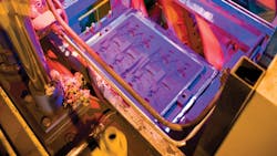
An innovative system, specially designed for the inspection of sand cores, core packages, and green sand molds makes use of the so-called ‘shadow modulation technique’. It is a pragmatic, easy-to-use and cost-effective qualitative inspection solution.

The shadow of an object contains fundamental information about its topography. The smallest defects such as cracks or breaks can only be identified once they are enhanced by their shadow. Many areas are hidden for the camera and are only visible through their shadow
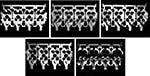
If you now use a multi-channel illumination set-up, you acquire a series of images that contains much more information than a single picture (Fig.2.) The second benefit of this approach is obvious: This system obtains a lot of redundant information (criteria visible in more than one image.) Redundant information leads to a very stable basis for making a good/bad decision.
However, not all areas are subject to the same quality criteria. The software needs to concentrate on user-definable “regions of interest,” which are actually relevant in terms of product quality. These regions of interest bring operator expertise into the system – important for a reliable evaluation. As a qualitative inspection system, it compares the item being tested with reference images.
Variations that are permitted within the production process should not be evaluated as defects, but should be tolerated. Images of several good parts form the reference dataset so the system is able to learn about the variation of the ‘good class’ of parts. Position correction, compensation for changes in the ambient light and passive or active dust protection make the system particularly sturdy for tough day-to-day foundry use.
Performing 100% inspection
The system must be fast enough to perform 100% inspection of every core and mold produced. Usually, it is connected to the PLC of the production line or to a robot, so that suitable actions can be triggered using the automatically generated inspection result.
Triangulation-based acquisition of range images — For castings, the situation is different. Surface variations that are not quality-related would lead to an unacceptable false-alarm rate when using 2D acquisition techniques. Especially for complex castings, manual inspection or 2D acquisition lacks reliable and comprehensive quality assurance. For manual inspection, the complexity of castings like cylinder heads, engine blocks or transmission housings causes unacceptable performance as features or defects would simply be missed. 2D (grayscale) inspection systems could be used for inspecting openings or other ‘simple’ tasks.
However, when it comes to complete surface inspection, these 2D systems would suffer from variations in the surface reflectivity, which are not quality related. Thus, triangulation-based acquisition of range images is the right choice. It scans the explicit surface profile and enables an almost all-over quantitative surface inspection of castings. It does not suffer from reflectivity variations, because it acquires the explicit height information of the surface. Different faces are presented sequentially to the vision system by an industrial robot.
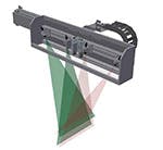

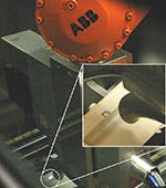
Typically, each scan takes about one to two seconds and provides approximately 5 million 3D data points. The fault detection and analysis is completed after an additional second, thus allowing the in-line inspection of 100% of the production. The attainable height resolution clearly depends on diverse design parameters in the set-up. A typical system achieves a vertical resolution of 0.1 mm on a lateral sampling grid of 0.2 mm × 0.2 mm. By using a robot, this system is extremely flexible: Different products can be examined by the same system, if necessary using different grippers. Beyond that, the test strategy can be chosen very flexibly, selected sides can be scanned several times in different situations, using different lasers and triangulation angles. If the cycle time is tight, the use of a multi-camera set-up can parallelize the data collection (Fig.4.)
The inspection routines are configured by means of a concise graphical user interface. All inspection results are stored in a database that can be queried from any networked computer. In particular, the operator at the rework station simply has to scan the Datamatrix code (or another one-to-one label) and immediately gets images of the defective faces with the exact locations of the flaws indicated2.
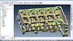
However, this technology also provides even more benefits: high-performance computer technology and the consistent improvement of up-to-date 3D techniques offers a complete comparison to CAD model (Fig.5) as well as extensive gaging, as at a CMM machine in the measuring room. But, we are still on the shop floor — 100% inline!
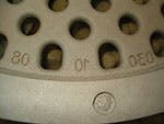
Laser marking for individual part identification — For the individual identification of castings produced in sand-based processes, a marking system engraves individual character strings. This marking system makes use of a high-powered, solid-state marking laser that ‘burns’ the characters out of the sand. This process is feasible in all kinds of foundry sands, including cold-box, hot-box, no-bake, inorganic and green sand. For sure, parameters differ and depend on the sand process that is being used. However, as a rule of thumb you can engrave, for example, six characters of 8-mm character height, 1-mm line width and depth in approximately 6 seconds (Fig.6.)
In addition to the marking laser, there is a need for some peripheral devices, like a cooling unit, exhaust and extraction system, etc. However, the main focus must lie on the laser protection, because unsecured these types of lasers are very dangerous to human eyes and skin. Therefore, by the design of the marking station, the laser needs to be encapsulated when in operation. It is necessary to design a turnkey marking station labeled as Laser Class 1 for safe operation in the foundry process (Fig.7.)

The strategy for applying a unique code to each casting differs and is highly dependent on the foundry’s production process. As an example, one foundry uses two laser systems in highly specialized and automated production lines. The individual labeling is introduced directly on the side of an engine block core package. In a third line they need to be more flexible, as up to eight different products are produced in the same molding line. Here, the strategy to work with ‘insert cores’ has proved its worth (Fig.8.)
Comparable flexibility could be achieved by using the laser directly at the molding line. Here, you can mark the cores in the mold or the green sand directly. However, this involves two notable details to be considered: First, you must bring the laser to the sand and not vice versa (e.g. by means of a robot); and second, depending on the number of cavities in the mold, cycle time could become an issue. That implies that this technology currently is not applicable for vertical molding.
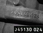
3D reading for reliable results — How can we track and trace the labeled castings through the finishing process (Fig.9)? We have already learned that casting surfaces are problematic for regular inspection based on grayscale image acquisition. For an OCR (optical character recognition unit) the situation is the same: variations in the surface reflectivity would cause unacceptable reading rates.
Since the information does not manifest itself in the reflective properties of the part but rather in the relief, 3D techniques are the appropriate method, providing high recognition rates and robustness even if rust, scratches, or traces of sand are present. By means of the stripe projection technique the relevant shape information can be recorded.

The deviations from a reference part without marking presents the information you require (Fig.10a), which has to be projected or unrolled onto a plane (Fig.10b) to obtain a grayscale image with high contrast (almost a binary image, Fig.10c.) Afterward, the information of interest can be extracted by standard optical character recognition (OCR) routines (Fig.10d.)

During the acquisition time of 1 to 2 seconds the part must not move; during the calculation process, which takes about 3 seconds, the movement can be resumed. (Fig. 11.)
Available design freedom should be used to boost the recognition rate by using fonts optimized for OCR (i.e., OCRB), avoiding similar symbols like 0, O and Q, incorporating validity checks or purposefully introducing redundancy like a check digit. Reading rates beyond 99.9% can be achieved3.
Automating inspection and traceability
Combining automatic visual inspection and traceability strategies gives the maximum achievable production quality assurance. The aim is to reduce customer complaints to the absolute minimum. As a further advantage, the results of automated inspection systems linked to a dedicated small batch of products provide an invaluable basis of information for further process optimizations. The automotive industry, as the largest consumer of foundry products, is increasing its demands on customers to provide such systematics with regard to product quality.
The technologies already are available and have proven their reliability in the foundry process. When they retire for the evening, production and quality managers are supposed to fall asleep easily instead of counting sheep!
Dipl.-Phys.Ing. Thomas Winkel and Dipl.-Ing. Dirk vom Stein are affiliated with inspectomation GmbH, Mannheim, Germany, which develops technology and systems for quality assurance, visual inspection, and traceability for foundry processes and products. Visit www.inspectomation.de
References
1. Prof. Beyerer, J.: “Quality Assurance in Foundries using Automated Visual Inspection Techniques”, Technical Forum on GIFA 2003, Düsseldorf (2003.)2. Dipl.-Ing. vom Stein, Dirk: “Automatic Visual Inspection Techniques for Holistic Quality Assurance in Modern Foundries”, Technical Forum on GIFA 2007, Düsseldorf (2007.)
3. Dipl.-Ing. vom Stein, Dirk: “Automatic Visual 3-D Inspection of Castings”, WFC – world foundry congress (2006.)