In permanent mold (PM) casting, also called gravity diecasting, liquid metal is poured by force of gravity into reusable metallic molds. This is one of the various, precision casting methods utilizing permanent molds in which rapid solidification permits the almost immediate shakeout of castings, greatly reducing production cycle time and improving the mechanical properties of the cast parts.
A typical permanent mold design with a vertical parting line to cast connecting rods and covers for forging presses of ductile iron (Figure 1) includes a mold cavity with central sand core having two core prints in each half of the mold, sand pouring cup, which also acts as the riser, water-cooling, and ejection systems. Liquid metal is poured into the pouring cup, then passes through the filter and openings at the bottom of the cup, filling the cavity previously treated with a protective coating.
The thermal impact of liquid metal flow in the mold is the major determinant of mold life, as well as casting quality. The permanent mold process typically operates within a temperature range of about 150-300° C (300-600° F), and the mold material is subjected to liquid metal erosion and thermal stresses. For the conventional PM casting of irons, molds are usually made of iron, steel, or copper. Gray cast iron with Type A graphite is a recognized mold material that offers good thermal conductivity and heat resistance.
Protective Coating
A protective coating is used to provide an insulating barrier between the molten metal and metallic mold to protect the mold from thermal shock and keep the metal from adhering to it. The coating reduces friction and thermal losses , in turn, preventing premature solidification of the metal in the mold. The coating drastically extends the mold life.
The coating usually consists of two layers. The first is a protective thermal barrier applied onto the mold cavity. This is a semi-permanent coating that must be reapplied periodically. The second is a lubricant (usually a carbon-containing material) that is deposited on the mold surface before each pour. It may be a water-based refractory coating sprayed onto preheated mold surfaces or solid ceramic coatings applied by thermal or plasma spray techniques.
Mold Cooling
The PM’s cooling system greatly affects mold life and casting quality. Relative to quality, the PM temperature is important in order to ensure that desirable thermal gradients in the mold are established, thereby regulating the casting’s solidification. In terms of mold life, hot or cold spots in the mold must be controlled. Uniform cooling prolongs mold life by eliminating localized areas of thermal shock or liquid metal erosion.
Abrupt changes in the cooling rate in the mold cavity caused by cold or hot spots are detrimental to casting quality. They cause shrinkage-related defects and hot tearing. In addition, uneven solidification produces a high level of residual stresses in the casting that result in dimensional instability during processing and service.
A properly designed cooling system regulates heat flow and ensures desirable productivity of sound castings and prolongs mold life. Careful consideration must be made to the priority of cycle times and mold life. If the operational mold temperature is kept within a narrow range, it will extend the life of the mold, but at the cost of increased cycle times.
To ensure properly regulated temperature in permanent molds, two primary methods for cooling exist — air and water. Each has advantages and disadvantages that need to be evaluated. Air cooling, for example, gives a very “soft” cooling rate, and effectively transfers heat from the mold when thin-walled castings are produced, but it is less effective than water cooling for the production of thick-walled castings.
Air is a simple method of PM cooling. But, it has limited capabilities because heat transfer from the mold to the air often isn’t enough for the production levels required by most foundries. To enhance air’s cooling capabilities, cooling fins and compressed air can be used, and contours can be designed into the mold to allow the air access to internal segments.
Figure 2(a) illustrates an air-cooled PM in which the back of the mold shell is contoured to maintain uniform mold thickness around the mold cavity. The contour of the mold back may be thickened or thinned as needed to increase/decrease the cooling rate in localized areas. Cooling fins are placed across the back of the mold to facilitate cooling. The back of the mold can also be designed flat, as shown in Figure 2(b), rather than contoured with the addition of cooling fins with either a circular or rectangular cross section. Rectangular fins have an obvious advantage due to the increased surface area. The back of the mold can also be designed without cooling. The air cooled mold has a longer service life because it is subjected to less thermal shock.
Water cooled molds utilize diverse designs. The following is a description of some of those more frequently used.
Cooling Jacket Welded to Mold — In this design, the water jacket is welded to the back of the mold. Heat dissipation is achieved by circulating water through the jacket. This allows the back of the mold to be contoured so that the coolant can reach throughout the mold and maintain uniform cooling. This system is effective in reducing hot spots and for increasing mold life by thermal shock elimination.
The only limitation is that the mold must be made of steel to allow the water jacket to be welded onto the mold’s back. Low carbon cast steel water cooled permanent molds with a wall thickness of 25-40 mm (1-1.5 in.) have longer life because mold cracks and other deteriorated areas may be periodically repaired by welding.
Cooling Jacket Affixed to Casting Machine — This cooling system is more moderate than the previous design because cooling is indirect. The main drawback of this system is the air gap that may occur between the mold and cooling jacket. This gap is due to mold thermal stresses and distortion that may occur during operation. As a result, some areas of the mold will have no contact with the water jacket and cooling will be slower and less effective. The water jacket can be made from a variety of materials, including steel and iron, and is suited for relatively small and thin-walled casting jobs, as well as operations that require frequent mold changes.
Drilled Cooling Passages – These may be placed relatively precisely in the mold, often adjacent to difficult-to-cool sections within the mold. The design’s major disadvantage is its inability to set up uniform or differential cooling.
The technique also presents problems during the drilling of passages. Since the passages must be straight and perpendicular to each other, elaborate drilling patterns are required. After drilling, excess openings must be closed with threaded plugs. However, these may leak due to differences in thermal expansion between the mold and plug material.
Once plugged, the mold must be pressure tested to ensure against leaks. If testing reveals mold material porosity, the mold must be scrapped. A leak may not even become evident during testing. Some are discovered only when the mold is heated during use, turning a small defect in the material to a large and dangerous problem.
Pre-Fabricated Piping in the Permanent Mold – Pre-fabricated cooling passages may be designed with one water circuit or two separate circuits. In this method, steel pipe is pre-fabricated to a desired cooling pattern, then cast into the iron mold during production of the mold blank. This method allows water to pass directly across any areas that would need cooling without restriction to straight line distances. Another advantage of this system is the elimination of mold leakage problems.
Spray or Vaporization Cooling of Permanent Molds — In this design, vertical passages in the mold are sprayed with water from nozzles located in the top manifold. As water contacts the hot surface of the passages, it changes from liquid to gas (steam). The energy required for this conversion is captured from the mold heat, thereby reducing its temperature. Condensed water is collected at the bottom by the collector manifold. The cooling passages can be cast into the mold blank or machined so that an elliptical (rather than circular) cross section is achieved. The elliptical shape provides greater surface area for more effective heat transfer. The commonly used mold material for this system is iron or copper. Although this process is one of the most effective cooling methods, it is less uniform. This lack of uniformity causes more thermal shock to the mold and, therefore, reduces mold life. Water cooling systems require proper maintenance to ensure the passages do not become clogged with scale from minerals in the water. To combat this, de-mineralized water can be used, or passages must be cleaned regularly.
Chills/Heat Sinks — Using metallic inserts or internal chills, commonly called “heat sinks,” made of a material with higher thermal conductivity than the mold material, is another way to enhance mold cooling and control casting solidification rate. This is a powerful tool for reducing the threat of hot tearing and shrinkage in PM castings. Placing metallic inserts into the mold will alter the heat transfer rate from thick sections of the casting and accelerate the solidification process in that area. To produce sound ductile iron, the goal is to set up directional solidification. Normally, a proper risering system is used to achieve this, but in some instances the casting design makes it impossible. In this case, an insert can be placed near thicker casting sections to enhance solidification. The main advantage of inserts is that there is a wide selection of insert size, shape, and material.
Figure 8 illustrates a thick hub wheel/pulley and four possible locations of heat sink/inserts to accelerate the thick hub cooling rate and control solidification.
Figure 8A shows a flat-ended insert on one side of the casting at the hub location. The insert draws heat from the hub so the hub and adjacent rims solidify simultaneously. Figure 8B illustrates how a projected-end insert is used to draw heat out of one side of the hub. The advantage of this is that the projected-end can reach further into the casting to more effectively draw heat out. If this set-up is not sufficient, two inserts can be used as shown in Figure 8C. If more rapid cooling is needed, a water cooled insert could be used as shown in Figure 8D. This is the same as a single projected-end insert design, except this insert has internal water passages for a higher cooling rate.
Permanent Mold Automation and Sequence
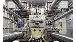
Permanent molds may be mounted on single head stationary or tilting PM machines operating in an opening-closing cycle as illustrated in Figures 9 and 10.
For high volume production, multi-station (4 , 6, 8, or 12 stations) semi-automatically operated carousels (turntables) that automate mold pouring, mold opening, casting knockout, and mold recoating in a preset cycle (Figure 11) are used. Carousels for thin-walled and low weight castings rotate continuously in 2.5-3.5 min. cycles; for indexing-turntable carousels, total cycle time may vary from 5-10 min., depending upon castings’ wall thicknesses and weights.
The sequence of operations during the cycle is as follows: a mold is coated; the sand core is set; the mold is filled with metal; the casting is held in the mold until it solidifies; the mold is opened to knockout; and is prepared for a new cycle.
Process Advantages and Limitations
Today, PM casting is used to produce a variety of ferrous and nonferrous near-net-shape parts, which feature exceptional dimension accuracy and surface quality.
It is advantageous to use PM casting for high and low volume production of ductile iron (DI) castings. The benefits of the PM casting of DI include all benefits of this process, as well as the advantages of a higher undercooling rate, as compared to sand casting. This results in a reduced amount of magnesium that must be added to the base iron and, subsequently, in a lower residual magnesium content in the finished castings. The latter helps control solidification shrinkage, improves nodularity, enhances mechanical properties, and increases overall casting quality.
There are some design and technological limitations typical of the traditional PM casting of iron that might limit the use of the process in certain applications.
Not much data are available on PM cast ductile iron. This article summarizes our experience in production technology for the PM casting of DI and contains some recommendations on applications.
