Like all raw materials and resources used in industrial processes — such as melting in a metalcasting operation — electricity needs to be managed and controlled in order to be useful and effective. “Harmonics”, i.e., the variety of voltages and currents that develop within an electric power system as a result of non-linear electric loads, can be a source of power-quality problems, and may result in increased heating in equipment and conductors, or failure in drives or motors.
When the normal 50 Hz or 60 Hz sinusoidal wave that feeds ordinary electrical appliances and equipment becomes distorted, it not only contains the original waveform, the fundamental, but also a series of higher frequency sinusoidal waveforms that are multiples of the original waveform frequency. Harmonic distortion could be defined as the deviation of the voltage and/or current waveforms from the fundamental waveform. Figure 1 shows the fundamental frequency and the third harmonic, together with the final signal resulting from adding harmonic waveforms to the fundamental.
Most equipment can withstand some level of harmonic distortion, but the increase in higher order harmonic currents may cause overheating in cables, wires, transformers and motors, or cause interference with communication and computer systems. Excessive harmonic currents create excess kVA demand and reduce the power factor, which results in wasted energy.
Harmonics are generated by resonant and non-linear loads such as rectifiers and switch mode power supplies, which use nonlinear devices such as diodes, SCRs and IGBTs in their circuitry. Many items such as variable frequency drives and computer and cell phone chargers all produce some level of harmonics.
The widespread use of rectifiers, variable frequency drives, and non-linear loads in general prompted a need for regulation when the generation of harmonics and its impact on utility power equipment became obvious. The Institute of Electrical & Electronics Engineers (IEEE) Standard 519 established the theoretical values for harmonics and their calculations.
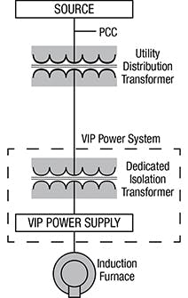
Total harmonic distortion (THD) is the ratio of the square root of the sum of the squares of the individual harmonics to the fundamental RMS value. THD is used to gauge utility line distortion. This standard and other international standards impose a limit on the total harmonic distortion of the voltage and current at the point of common coupling (PCC). The PCC is where the plant is connected to the utility line. Normally this will be the primary of the utility transformer feeding the plant, as shown in Figure 2.
Induction melting systems using diode/SCR rectifiers generate some amount of harmonics: the amount depends on the methodology used to control the rectifier (i.e., phase controlled and non-controlled rectifiers). A full fired, non-controlled SCR rectifier generates minimal harmonics compared to phase-controlled rectifiers that fire SCRs at different phase angles to control the output voltage of the rectifier.
The harmonics generated by the induction power supply can be reduced by using 6, 12, 18, 24, etc., phase input power, or by special filters. The use of multi-phase rectifiers lessens the harmonic content of the utility line and enhances the line power factor. This approach requires line transformers with multiple phase-shifted 3-phase outputs and one rectifier connected to each of these 3-phase outputs.
Filters are offered according to different design methodologies and range from a simple capacitor and choke combination, known as passive, to an active injection filter using electronic switching devices to inject canceling harmonics into the utility line. Passive filter selection must consider the effect of changes to the line due to load addition or removal. Most filters are designed to remove certain frequencies and are dependent on the existing line characteristics. A change in the line characteristic could cause damage to the filter and the equipment attached to it. Note that filters of either type consume power, something that needs to be considered when selecting equipment.
The theoretical percentage harmonic currents generated by 6, 12, 24 and 48-pulse (3, 6, 12, 24-phase) rectifiers are shown in Figure 3. The percentages of fifth and seventh harmonic currents generated by a 6-pulse rectifier are 20% and 14%, respectively. In a 12-pulse rectifier the fifth and seventh harmonics are eliminated. As the number of pulses increases, additional higher order harmonics are eliminated or significantly reduced.
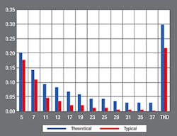
Figure 4 shows the theoretical and typical values of the harmonic currents generated by a 6-pulse diode rectifier.
The power utilization of electrical equipment is determined by power factor (PF). Note that in many areas, low line power factor will result in penalties on electric bills. In a rectifier the power factor is the product of the displacement power factor (cos φ), which is due to the phase shift between current and voltage and the distortion power factor, which is inversely proportional to the THD.
The displacement power factor in a non-controlled rectifier is very close to unity. Therefore, a rectifier’s total power factor is mostly dependent on the distortion power factor.
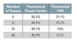
Figure 5 shows the theoretical power factor for each different number of pulses. As the number of pulses increases, the power factor increases. The typical %THD for 6 to 48-pulse diode rectifiers are 21.5%, 6%, 2%, and 1.4%, respectively.
Line distortion is a serious issue that must be addressed by designers and users of induction melting equipment. IEEE Std. 519 and other international standards determine the level of harmonic distortion allowable on the utility lines at the PCC.
It is imperative that a study of the harmonics content be performed prior to equipment selection. This study not only requires the operating characteristics of the equipment being considered but also the utility line short circuit current (ISC) at the PCC to determine the harmonic impact of the 7.6% equipment being considered.
Michael Looby is a District Manager with Inductotherm Corp. Visit www.inductotherm.com or email [email protected].


