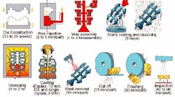
Figure 1. Schematic shows manufacturing of an investment casting.
Figure 2: Potential porosity locations in original design.
Figure 3 : Solidification plot for original design.
Figure 4: Solidification plot for modified design.
Figure 5: Potential porosity locations in modified design.
Figure 6: CAD drawing of the stepped cylinder pattern.
Figure 7: Three kind of meshes. (a) midplane; (b) fusion; (c) 3D
Figure 8: Filling time and solidified material for the first injection point, with the three types of mesh. First column: Filling time/profile. Second column: %frozen
Figure 9: Injected parts using the first injection point (a), the second injection point (b and d), and the third injection point (c)
Figure 10: Results for the second injection point with midplane and 3D meshes
Figure 11: Results for the third injection point with fusion mesh
Figure 12: Interrupted filling experiment to determine the last section to be filled and comparison with MoldFlow results
Investment casting involves using an expendable pattern made from a variety of materials, such as wax, frozen mercury, or plastic, among others. The term investment casting is derived from the characteristic use of a mobile slurry, or investment, to form a mold with an extremely smooth surface and high dimensional tolerance. (See Figure 1 for a schematic of the investment casting process.) .
When wax is used as a pattern material, the process also is referred to as lost wax investment casting process. Lost wax casting process is one of the oldest techniques, dating back to 4000-6000 B.C., and may have been used by early humans to produce rudimentary metallic tools. For centuries this technique has been used to manufacture jewelry and artisanal works.
Modern investment casters must adopt current technologies to remain competitive. The capability to produce investment cast components of high quality, while reducing production costs and development times is an ongoing challenge for all metalcasters. Increasingly complicated parts are being made by investment casting with alloys that are more difficult to cast, and for several years computer-aided modeling has been helping foundries not only with the design of new components, but also to redesign existing products. By eliminating product defects and reducing scrap and rework, investment casters can improve their products, and achieve more consistent quality and higher yields.
Even though computer-aided process simulation has been available for the past 15 years, many investment casters still use the conventional trial-and-error approach for process development. In many foundries, new cast components often are put together by different departments working independently of each other. When a new customer's need is identified, the design group generates the part drawings. Then, the engineering department identifies the mechanical stability and establishes guidelines for finalizing the component's design. Finally, the foundry brings the component into production, conforming to the stringent specifications provided by the designers.
Inevitably, the operators are under pressure to produce excellent castings within a tight schedule and budget. Unfortunately, a traditional approach rarely allows the operators to participate in the design and engineering phases prior to the costly production stage.
Thanks to advanced computer-aided technologies and casting process modeling, the traditional approach is becoming a thing of the past. Process simulation provides valuable information that facilitates participation by the foundry engineer early in the product development stage, which reduces the time between the concept stage and production stage in the life of a new component. Also, simulation has been shown to be an effective educational tool in the foundry industry. The goal is to model all of the underlying physics of the process accurately, so that important process variables may be identified and effectively controlled. By visualizing the entire casting process in a virtual environment, problems associated with fluid flow, solidification and part distortion become apparent to the designer and foundry engineer.
Simulation also allows testing of novel component designs and process modeling techniques, along with re-engineering designs in the early stages of development. By the traditional approach this would be undesirable due to the high cost associated with trial and error on the production floor. In order for computer-aided modeling to be implemented successfully into the design stage, it should perform a wide variety of tasks.
Process simulation must have the capability to model the properties of a wide range of casting alloys accurately. Also, the nature of investment casting products can pose several difficulties to the modeler. Due to the highly complex nature of the investment casting part and gating design, especially in the aerospace industry, simulation software has to model the process accurately in order to be of any significant use to the foundry engineer. The predictions that are derived from modeling strongly depend on the ability of the software to model the heat loss in the mold.
Because mold cooling in an investment casting process primarily takes place through radiation, view factor calculations must accurately predict the self-radiative effects in all areas of the casting assembly. The casting solidifies by cooling though contact with the ceramic mold, and the contact conductance varies with geometry and time. Further, to model the whole process realistically, the material data supplied should be at elevated temperatures describing the thermal behavior of the material in the mushy state.
Highlighted here are some case studies for the investment casting process. In some cases, the original casting design produced poor quality castings, others had low yield. Analyses were performed using the simulation software to modify the existing design, producing sound castings and improving part yield.
Simulation steps
The process involves a number of basic steps, which can be broadly divided into the following: a) Producing a die for making disposable or expendable patterns. b) Making expendable patterns along with a gating system. c) Precoating the pattern assembly. This is done by dipping the gated pattern in an agitated slurry and stuccoing fine-grained sand as the first layer of coating. The first coat is critical because it establishes the surface texture and determines how cleanly the mold will strip. d) Investing the pattern assembly for the production of molds. Investment molds may be made either by shell molding or solid molding. In the shell molding process successive layers of refractory are coated on the precoated pattern surface, one after another, providing ample time for the layers to dry. This may be repeated six to eight times to make a shell roughly 6 mm thick.
The shell molds thus obtained are quite strong. In solid molding, suitable slurry made of refractory material and binder is poured around the precoated pattern assembly and allowed to set. e) Removing the pattern material by heating from the solid mold or shell mold. f) The shell molds are poured free standing onto a bed of sand. Solid molds can be poured in the conventional way. g) After solidification the mold is destroyed to retrieve the near-net-shaped castings.
Simulation improves layout
Designing the set up and orientation of investment cast parts calls for balancing two priorities: maximizing the number of parts produced with a single pour; and minimizing part congestion, which leads to defects. For any single job, a virtually infinite number of combinations exists in varying number of parts, part orientation, and gating and runnering. The process engineer must rely on previous jobs to estimate a set-up that will produce quality parts. At best, this set-up is not optimized to provide the highest yield. At worst, this trial-and-error method of design will produce defective parts. Using casting simulation software, this guesswork is eliminated. Problems due to filling, part cooling, effects of neighboring parts, and solidification, are all identified and able to be corrected before the first pour.
The following example, involving production of parts for medical implants, presents an improper feeding issue being solved early in the design process, reducing the overall project time without wasting material. The foundry's goals included production of the parts at a high throughput rate with high quality and precision. Therefore, each pour had to produce a large number of defect-free implants. To meet these requirements, a tree-type set up was used with four runners. Due to heat transfer and solidification concerns, 24 parts were placed on the tree in a staggered formation to reduce part congestion. This design idea was then analyzed using ESI Group's (www.esi-group.com) ProCast software, which accurately calculated the effects of fluid flow, self-radiation, and solidification.
The initial design showed that, due to the filling order and self-radiation effects, there would be shrink defects in many of the implants. The filling order supplied hot metal to extremely varied locations in the cavity, affecting feeding and heat transfer rates. The location of the part on the tree greatly affected the size of the defect. Due to self-radiation, those parts in the center columns suffered larger defects as the surrounding parts kept the large bulky head hot, as shown in the shrinkage porosity indicator of Figure 2.
The bulky sections of the implants tended to hold heat much longer than the rest of the part; therefore, feeding paths back to the gate were cut off prematurely, producing shrink defects. The fraction solid plot in Figure 3 shows this affect. The solid metal (gray) encloses the hot metal (red). There were two primary solutions for improving the part quality: reduce the number of parts on the tree, thereby eliminating self-radiation effects, which were keeping some of the parts much hotter than others, depending on their position on the tree; or, increase the gate size to keep the feeding path open longer. Obviously, reducing the number of parts in the set up drastically reduces efficiency per pour. Therefore, the gate size was increased moderately.
The resulting analysis from this modified design showed the increased gate effectively kept the feeding path open. Figure 4 presents the fraction solid through the implant. The continuous path of hot (red) metal indicates an open feeding path, eliminating the shrink porosity, as shown in Figure 5. This increased gate also provided a more consistent filling pattern from the bottom of the tree upward, reducing spillover and splashing effects.
This project demonstrates how, in a very short period of time, computer modeling displayed the problem with the original casting design and verified a new design concept, which eventually lead to a better solution. Verification using simulation requires much less time to achieve a quality result, and with no material costs, rather than depending on the conventional trial-and-error methods on the production floor.
Simulating the injection process
The prediction of the motion of the filling front was considered reasonable, so the next step was to predict the formation and development of defects. The experiment consisted of filling a die to make the stepped cylinder depicted in Figure 6. Three different injection points can be used, so mold filling and solidification can be studied under a wide range of conditions.
The die was made of aluminum, so only the surface defects can be compared between the experiment and the simulation. The part was produced using different process parameters (wax temperature, injection pressure or flow rate). The use of different injection points leads to the development of different defects. These tests permitted the assessment of the model capability to predict these defects using Moldflow Corp.'s (www.moldflow.com) simulation software.
MoldFlow allows use of three kinds of elements (Figure 7). The first mesh is named midplane. With this kind of model, the geometry is approximated by its mean surface, and all the properties are calculated on the mean surface, defined as the surface which describes the midpoint of all the sections of the geometry. Thus, the model obtained is 2D. The problem then is to create such a model from a 3D CAD model.
The second mesh is called fusion. With this kind of model, the surface envelope approximates more closely the real geometry and is, essentially, a hollow model. The properties are then calculated on both surfaces, and their variations in the thickness of the geometry are estimated. The model obtained is 2.5D. It looks like a 3D model, but in fact it does not really consider the behavior in the thickness. The third mesh is true 3D. With this kind of model, a classical 3D approach is used, with 3D elements. Nevertheless, using this approach, some assumptions can be made to decrease the calculation time. These assumptions are linked to the flow of the material (fast algorithm or full, Navier-Stokes algorithm), and the importance of the inertial forces.
The results presented here have been obtained with the fast algorithm. The fast algorithm makes some simplification of the Navier-Stokes equation by neglecting the inertial forces. The calculation time is lower, but the predicted flow may not be as accurate as with the full Navier-Stokes algorithm.
Due to the increasing complexity of the models, it is expected that the calculation times will increase from the midplane mesh to the 3D mesh. For example, the simulation presented in Figure 8 used the three kinds of geometrical description.
For the flow of the wax, despite the presence of a model in MoldFlow, a second-order model was preferred, as it predicts the viscosity more accurately. The second-order model describes the viscosity as a second-order polynomial function of temperature and logarithm of the shear rate. The results presented here are for a filling time of 10 seconds, and a wax temperature in the nozzle of 70°C.
First injection point: The simulation results are shown in Figure 8. Figure 9 presents a picture of the injected part obtained using a filling time of 10 seconds, at a temperature of 70°C. The filling path predicted by the simulation with the three kinds of elements shows that in the thinner section half of the part is filled at the beginning of the injection, and half at the end. This probably results in a weld line where these two domains join. The freeze or solidified map shows that at the end of the injection, a significant proportion of the wax is behind the solidification point in the first filled area, whereas in the last filled area next to it, it is still mostly liquid.
In fact, MoldFlow will predict the weld line position in the case of the midplane and fusion meshes, and in these cases it predicts a weld line at the location where the two domains join. Figure 9a shows that on the injected pattern there is, effectively, such a weld line at this location.
Second injection point: The simulation results are shown in Figure 10. For these simulations,the predictions obtained with the three models are different. The midplane and fusion models predict a weld line above the injection point in the thinner section. Only the midplane and 3D results are presented in Figure 10. The 3D mesh predicts a mis-run in the same location, as shown on Figure 10c. The experimental results show that there is a weld line but no mis-run, Figure 9b.
Third injection point: The simulation results are shown in Figure 11 for the fusion mesh only. In this case, the simulation using the midplane mesh did not predict any weld lines, whereas the simulation using the fusion mesh predicted some defects on the bottom surface of the cylinder, near the injection point. The 3D simulation did not show any obvious surface defect. The experimental results shown in Figure 9c indicate a weld line due to a surface defect and an undulating surface. Figure 9d shows, for comparison, the same surface when injected using the second injection point.
Mold filling results
The results presented here have shown that the predictions of our model do not consistently align perfectly with the experimental results. The experimental results might be questioned, as in some cases the behavior predicted in the thin/thick die experiment implies a less viscous fluid, in the first and third in-gate, and a more viscous fluid in the second in-gate. As stated previously, that can be explained by the possible discrepancy in temperature and a possibly inadequate venting of the die. Nevertheless, it seems that the predictions are representative of the flow during the filling. The computation times to perform such simulations are very high, as most of the properties are temperature-dependent and the viscosity is temperature-and shear-rate dependent. Therefore, our model is strongly non-linear, and this is a disadvantage for any commercial application. For these reasons, some studies should be carried out to optimize the ratio between accuracy of the prediction (i.e. complexity of the model) and computation time, and simplifications, such as a density dependent only on the temperature, then could be made.
Defect prediction
These results show that MoldFlow is able to predict the development of these defects. The accuracy of the position of the defects is less clear. Experiments have been carried out with this same cylindrical pattern using the first injection point, with different wax temperature and different injection flow rates. The experiments used the technique of short shots, which consists of interrupting filling so as to be able to see the position of the filling front at different injection times. These short shot experiments allow the determination of the locations of the last parts of the pattern to fill, and measurement of the angle between the last parts to fill in the thinner section and the in-gate. Figure 12 shows an example of this and the numerical simulation results corresponding to the process conditions.
Advanced casting simulation tools like ProCast and MoldFlow allow the foundry engineer to quickly bridge the gap between design and manufacturing. Optimization or improved efficiency during the manufacturing cycle leads to substantial time and cost savings. Computer analysis provides the means for verifying design ideas and viewing the effects of what if's at minimal cost by avoiding time-consuming and expensive rework and retooling.
Shorter development times and cost reductions (scrap costs, re-engineering costs) are required to be competitive in the investment casting industry, and computer modeling with industrial and advanced solutions are an efficient way to achieve these goals. Simulation can be used at the very early stage of the design conception, i.e., concurrent engineering with customers. Modeling the investment casting process step by step with first thermal only models, filling, and solidification analysis before taking into account the full process complexity, allows engineers to develop a sound process. The process development lead time using virtual manufacturing proves always shorter than a traditional trial-and-error approach. Making use of state-of-the-art modeling technologies, additional investigations can be conducted to assess the metallurgical quality and performance of the product.
References
- ProCast User Manual && Technical Reference 1998-2005
- Ch. Pequet, M. Gremaud, M. Rappaz, Modeling of Microporosity, Macroporosity and Pipe Shrinkage Formation during the Solidification of Alloys using a Mushy-Zone Refinement Method, Met. Mater. Trans. 33A (2992) 2095-2106.
- Ch--A.Gandin, J.L. Desbiolles, M.Rappaz , Ph. Thévoz A three-dimensional cellular automaton finite element model for the prediction of solidification grain structures, Metall.Mater. Trans. A, in press
- J--C. Gebelin, M.R. Jolly, A. M. Cendrowicz, J. Cirre and's . Blackburn: Met. Mat. Trans.B, Vol 35, No 4, August 2004.
- S.. Chakravorty: 24th BICTA Conference on Investment Casting, paper 1, 6-8 June 1999,Oxford, UK
- D. R. Lide: Handbook of Chemistry and Physics, 74th edition, CRC press Inc., BocaRaton, Florida, 1993, pp 6.144-6.147
- S. Jones, M.R. Jolly,'s . Blackburn, J.C. Gebelin, A. Cendrowicz and K. Lewis, Measurement of Autoclave Thermal Profiles During High Pressure Steam Dewaxing of Investment Shells Part 2: Wax Body Profiles, Journal of Material Science and Technology, in Press
Hu Hong-Jun is a professor in the Dept. of Material Science and Engineering at China's ChongQing Institute of Technology, in ChongQing. He may be contacted at [email protected].
