By Ralph A. Felice
Successful investment casters know the importance of process control in producing quality castings. Some of the key variables in the casting process include mold temperature, mold insulation characteristics, cycle timing, and operator technique, but the most critical of process variables is metal temperature.
Non-contact measurement of metal temperature for investment casting presents numerous serious difficulties, and the significance of temperature errors generally has not been appreciated. However, a recently developed device provides quantitative feedback of real-time accuracy and indicates potential problems.
Importance of temperature
Metal temperature is a dominant factor in investment casting, especially in the "equiaxed" process, where it has a direct effect on solidification, and thus on many quality characteristics. If not properly measured and controlled, variations in metal temperature can affect one or more of the following:
- Finished casting dimensions
- Grain size
- Porosity (surface and internal)
- Mechanical properties
- Product integrity, i.e., propensity for hot tearing
- Fill of thin sections
In addition, there is potential for increased inclusion defects due to crucible erosion and/or damage to pouring cups, filters, and cores.
Consequently, improving metal temperature measurement and control will enhance quality and productivity, will reduce maintenance and labor costs, and has the potential to decrease testing and liability costs.
Difficulties with temperature measurement
Investment casters, particularly those using vacuum induction melting equipment, generally use some type of non-contact infrared radiation thermometer, or pyrometer, as either the principal or secondary means of metal temperature measurement. Users of conventional pyrometers may not be aware of the potential sources of error in their measurements, and simply looking at the instrument's "accuracy" specification provides a misleading picture. These accuracy specifications refer to ideal targets in laboratory environments. Realworld sources of error, leading to surprisingly high measurement uncertainty values, include (but are not limited to) the following:
- Unknown /changing emissivity — Multiple alloys, turbulence effects, temperature and wavelength dependence, and composition changes during processing all contribute to the unpredictability of the emissivity.
- Vapor emissions — For highpressure melting (near and above atmospheric pressure), offgas from the melt or crucible can add to or subtract from the thermal radiation, causing error in either direction.
- Sight port obstructions — For most instruments, any reduction in signal results in lower indicated value of temperature; dirt on the window affects most pyrometers; metal deposited on windows is the most serious problem.
- Sight glass material: uniformity and condition — not all glasses have the same transmission characteristics; some are 'gray', but others have transmission that changes with wavelength. This can confuse conventional pyrometers.
- Calibration — The industry standard is calibration once per year, but instruments drift and fail on their own schedules. Calibration is ideally done with all the optical elements used in the factory (sight glasses or mirrors).
- Instrument alignment — through-the-lens aiming requires two optical paths to coincide exactly, a statistical improbability; this affects all classes of conventional pyrometer.
These difficulties are specific to optical temperature measurement. There are also process-related difficulties that complicate temperature measurement for any type of instrumentation, including:
- Acceptable range for process variables — Unless the entire melt is at steady state, which is usually not practical, there will be a range of temperatures during casting; it is important for that range to be within the product's good quality limits.
- Signal processing capabilities — Each A/D or D/A conversion between measuring instrument and control equipment is a source of potential error; wide analog ranges lead to lack of precision.
- Melting technique — Poor technique can lead to excessive boil-off of high-vapor-pressure elements, turbulent melt surface, or formation of reaction products, all of which cause errors in conventional pyrometers. co ntinued
- Ingot / crucible / coil matching — The relationship among these three components of the melting system is important with regard to the attributes of the melting cycle. Improper matching can cause slow and uneven melting, local superheating, and/or spitting. Again, all of these are sources of error for conventional pyrometers.
Rationale for pyrometry
The reason to choose pyrometry is that it has inherent advantages: it is non-contaminating and immune to the poisoning of contact sensors; it is easy to deploy; measurement is continuous; there are no consumables; and catastrophic failure (loss of measurement capability) is rare.
Now, progress in the science of pyrometry has addressed the problems associated with real-world use. The SpectroPyrometer, an entirely new kind of instrument, is an expert-system, multi-wavelength pyrometer with a track record of solving these problems.
Solutions to pyrometry problems
The SpectroPyrometer has dealt successfully with unknown and changing emissivity for a variety of metals and alloys, both liquid and solid. It detects and discards radiation affected by absorptions or emissions from process gas. It can function with a partially obstructed path and can use any sight port; sight ports can be field-checked for their suitability and can even be calibrated into the system in the field if necessary. It uses a fail-safe system of alignment and tells the user if it is in need of calibration. It can be calibrated in the field to avoid the cost of purchasing and maintaining spares.
The SpectroPyrometer does more than provide superior real-world accuracy. It gives a real-time readout of the quality of each measurement, the tolerance, which is the uncertainty in degrees for that measurement. It also provides the signal strength, a comparison of the target to an ideal target at the same temperature and conditions. These two features provide valuable information about feedstock and process conditions; they can help ensure the correct alloy is being used and show whether or not alloying materials are boiling off. Even more advanced applications will become apparent to users with access to this information.
In various installations, the SpectroPyrometer has addressed and solved these difficulties with non-contact temperature measurement.
Emissivity — The real problem with emissivity is that it is not an unchanging property of a material: it can change with each sample of that material. Emissivity, of course, is the factor that relates theoretical calculations to real-world behavior in pyrometry. It
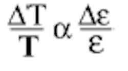
is nothing more than the efficiency of a radiator: a perfect radiator has an emissivity of one; an imperfect (real) radiator has an emissivity of more than zero and less than one. Unfortunately for investment casters, the emissivity of metals is extremely variable. For any one sample it depends on composition, contamination, surface finish (for liquids this corresponds to turbulence, and is a huge factor), mechanical and thermal history, the wavelength at which the measurement is made, and the temperature itself. How much does uncertainty in the value of emissivity affect the temperature? Analysis says that the relative error in temperature is proportional to the relative error in emissivity:
are the errors in each.
For investment casting, the values of emissivity for liquid metals have most often been observed to be in the range of 0.15-0.30 and the small value of emissivity in the denominator ensures a large effect in temperature error. For example, consider an alloy that has an actual emissivity of 0.26, but the instrument is set to a value of 0.30; then the error in measured temperature will be (0.30-0.26)/0.26, or more than 15%. In practical cases this can mean errors of many hundreds of degrees Fahrenheit (for a real case, see Figure 41).
A casting shop may offer parts made of 20 or 30 different alloys. Little work has been done to quantify the emissivity of metals that vary by small amounts of alloying materials, so the emissivity is not available from a handbook for investment casting alloys. Similarity of composition cannot be used to estimate emissivity. As Figure 1 (see p.40) shows, small amounts of additives can change it greatly, sometimes with unfortunate results. The two alloys whose emissivities are shown vary in composition by a total of about two atomic percent of added elements. The resulting difference in emissivity caused conventional pyrometers, "calibrated" on one alloy, to misread the other by several hundred degrees. The large error caused process upsets that put furnaces out of production for days and necessitated laborious hand-cleaning of the vacuum vessels. The graphs of Figure 1 are a byproduct of a single SpectroPyrometer-temperature measurement for each composition. (The instrument can save its data for archival purposes and analyses such as this one.)
Additionally, some alloys are proprietary and would therefore never be found in a handbook of investment casting emissivity, if such a handbook even existed. 1 Despite this, suppose for a moment all the emissivities of all the alloys were known, and that the effort were made to perform all the bookkeeping to ensure that a conventional pyrometer was set to the proper emissivity value when each alloy was being cast. The changeability of emissivity with operating variables such as temperature, turbulence, and composition would still cause errors in temperature measurement. Clearly, a better way is needed.
It was this reasoning that led to the development of the SpectroPyrometer, a pyrometer that does not require any prior information to give accurate temperatures, no matter what the emissivity or the environment is doing.
In numerous real-world applications since 1997, the FAR SpectroPyrometer has consistently achieved this goal. Figure 2 (see p.41) shows the temperature and emissivity from the log of a SpectroPyrometer monitoring a nickel-based investmentcasting alloy. Several interesting features are shown on this graph. First, each change in the power setting is seen to result in a rapid, spike-like increase in emissivity. This is caused by the electromagnetic stirring of the melt which causes turbulence. Turbulence is known to enhance emissivity: the motion of the liquid forms small cavities that increase absorption and emission due to multiple reflections.
Next, the emissivity is seen to undergo a step-like change while the melt is cooling: the emissivity decreases more than 10% from 0.245 to 0.220 at around 1:15 hours. This effect, coupled with the temperature holding constant while this change occurs, is consistent with alloying materials boiling off. Finally, the melt freezes, and emissivity changes drastically from about 0.22 to 0.60. The slowly decreasing temperature and concurrent slowly increasing emissivity indicate the metal hardens by going through a slushy state rather than an abrupt phase change, like water to ice.
Figure 3 (see p.41) shows the same episode, but this time the output of a conventional pyrometer is added. Besides the large error in temperature, note the impossibility shown by the conventional pyrometer during the power-off cooling: it reports temperatures increasing from about 1:35 to 1:50. This is an artifact due to the emissivity increasing as the metal cools; all instruments of this type would show the same error.
The difference between the measurements of the two pyrometers is shown in Figure 4 (see p.41); this is the error for the conventional pyrometer during this test. The tolerance returned by the SpectroPyrometer for the same time frame is also shown. This number reflects how well the temperature is known (to an average of 8°) and gives the operator confidence that all is well.
What do the large temperature errors caused by incorrect emissivity mean in actual operation? Besides the effect on product quality due to incorrect metal temperature, some of the obvious results are wasted power, longer cycle times, and harsher refractory wear. This can be seen in the following comparison. The two traces in Figure 5 (see p.46) show the temperature and emissivity returned by the SpectroPyrometer for several successive casting cycles while the process was controlled by a conventional pyrometer. The peak temperature is not particularly repeatable and the emissivity is seen to have many substantial spikes indicating extreme turbulence.
The spikes are the result of severe electromagnetic stirring. The sequence goes like this: the turbulence in the melt enhances the emissivity, which the conventional pyrometer interprets as an over-temperature-value. In response, the controller turns off the power. The turbulence subsides when the power is removed, and an under-temperature is then sensed by the conventional pyrometer. The power is turned back on, and the resultant current surge violently stirs the melt. The cycle repeats, as can be seen in the spiky red trace. The violent stirring causes erosion of the refractory wall and hence inclusions in the product.
Contrast this behavior with that shown in Figure 6 (see p.46) when a SpectroPyrometer controls the process. The emissivity scale is the same, the temperature increments are the same, but the temperature range is lower. The reason for this is the process is now accurately achieving the setpoint temperature because of the accurate measurement by the SpectroPyrometer. Note that the temperature trace smoothly reaches the setpoint and controls closely about it until each cycle ends, all with the same controller and control algorithm.
It's also clear that the spikiness indicating the turbulence of the melt is greatly reduced. The repetitive power on-off sequence caused by and causing turbulence has been broken. There is still some turbulence from electromagnetic stirring of the melt during full power heat-up, but with accurate temperature control despite the changing emissivity, the setpoint is smoothly achieved and turbulence subsides.
The advantages of the improved control are greater quality from less high-temperature boil-off and reduced inclusions (from reduced refractory erosion), higher yield from faster casting cycles which reach the actual setpoint instead of an artificially high value, lower maintenance costs from lower refractory erosion, and lower power costs from decreased power usage.
Vapor Emissions — It is well known that metal may be lost to boil-off during processing. What may not be so well known is that the resulting metal vapors, plus offgas from crucibles, susceptors or other furnace furniture, can affect pyrometric measurements by selectively absorbing some of the melt's thermal radiation. The reason that these effects are not common knowledge is that conventional pyrometers neither save the thermal data, nor do they have the wavelength resolution to distinguish the problem. The SpectroPyrometer has observed vapor absorption in numerous environments.
An example of an absorption spectrum is shown in Figure 7 (see p.47). The conventional pyrometer in use had a wavelength response in the middle of the affected areas and, consequently, huge errors. In true Murphy's Law fashion, the wavelength range around 650 nm where the absorption is the worst happens to be the most common range for pyrometers. The amount of the error depends upon a combination of the instrument's wavelength response and the magnitude of the absorption. In this example the error was around 400°C, about 25%.
These environmental effects have been seen at near-atmospheric or elevated pressure, so it is likely that air-melt investment casting operators need to consider the vapor-phase problem.
Sight Port Obstruction — All investment casters should be concerned about the deposit of metallic vapors on cold surfaces. If the surface happens to be the sight port, the transmission characteristics can change and cause large errors. The SpectroPyrometer recorded a catastrophic deposition of copper on a sight port, caused by the melting of a water-cooled copper electrode in a vacuum furnace. The thin-film deposition of copper on the window caused absorptions that changed with wavelength in a pattern not seen in natural materials; the inaccuracy this caused was reflected in the SpectroPyrometer's on-line tolerance readout. The resulting huge change in tolerance alerted the operators, who then changed the window. This restored the accuracy to earlier levels. The time evolution of this process upset is shown in Table 1 (see p.52).
The problem that resulted in the deposits was rooted in the incorrect readings of the conventional control pyrometer: the workpiece softened and slumped from the excessive temperature, contacted the copper element, and flashed it onto the sight port.
The reason for the change in tolerance was the deposit's unusual transmission. If the material deposited had been dirt instead of metal the SpectroPyrometer's temperature reading would not have been affected, but the signal strength display would have indicated the reduction in radiation reaching the detector. Most conventional pyrometers will return lower temperature values for dirty sight ports without alerting the operator.
Sight Glass Material — Ideal sight glasses are flat in wavelength response, at least over the range of the instrument with which they are used. The best transmission one can hope for is about 94%. The roughly 6% loss comes from reflection at each surface of the glass. 2 This means, in the very best of cases, most conventional pyrometers must be adjusted to accommodate the sight glass. If the instrument requires an emissivity input between zero and one, the way to make this correction is to multiply the (assumed) known percent transmission by the (also assumed) known emissivity. For example, a material with an emissivity of 0.30 in the range of a conventional pyrometer being used with an ideal sight glass of transmission 94% requires that a conventional instrument's emissivity be set to (0.30 × 0.94) or 0.282. While the difference may seem small, the same error analysis discussed earlier applies, yielding more than 6% error in temperature.
While the above analysis may seem burdensome, it is at least possible. The glass in the example has a single, known value of transmission for the whole wavelength range of the pyrometer. What happens when the sight glass is not ideal? The transmission shown in Figure 8 (see p.53) was measured for a sight glass in use in an investment casting foundry.
The problem with this type of sight glass is illustrated in Figure 9 (see p.53). The broad wavelength response of a conventional pyrometer has been superimposed on the intensities for two temperatures and the sight glass transmission. Because of the wide, undifferentiated wavelength response of the pyrometer, the effective average "emissivity" changes for the two temperatures. The reason is that there is no radiation for half of the pyrometer's response at the lower temperature.
The result is that it is impossible for a conventional pyrometer to be correct at both temperatures without readjustment of the emissivity (or the relative emissivity) between the two temperatures. This is obviously impractical. In contrast, the SpectroPyrometer has hundreds of very narrow wavelength bands (each with a bandwidth about the thickness of the lines showing the limits of the conventional pyrometer), which means it corrects each wavelength individually and avoids the problem altogether.
Calibration — From the analysis above, it is clear that pyrometers should be calibrated with whatever other optics are in use with them (sight glass or mirror.) In general, the industry standard is for calibration once per year. Unfortunately, this scheduled calibration is a compromise, just as scheduled maintenance is a compromise. The analogy to condition maintenance (maintenance done when some diagnostic indicates a problem is developing) would be "condition calibration." The ideal instrument would have a diagnostic that tells when it requires calibration or repair.
Experience has shown that pyrometers of all types are often found to be incorrect at the annual calibration. Inescapably, the instrument drifted out of specification some time in the previous year. Consequently, for some period of time it has been providing incorrect temperature values, with negative impact on the process. The SpectroPyrometer avoids this problem by alerting the owner through its tolerance function. A shift in component behavior, whether due to external optical damage or internal electronic failure, will immediately show up as an increased tolerance. This immediate warning prevents use of a compromised instrument and all the scrap and confusion that incorrect temperatures generate.
Instrument Alignment/ Aiming — Aiming a pyrometer may not seem challenging, but unfortunately it can be. If the temperature is not uniform across the workpiece, if the target is small or distant, or if a sight tube is used, spurious results can occur. Many portable and fixed pyrometers use so-called through-the-lens viewing. Everyone who has used a camera is familiar with the technique. The operator looks through a viewfinder and sees the target with the circle of the reticle in the center of the field of view. The reticle supposedly delineates the area where the temperature is to be measured. The way this is done optically is that the field of view is split into two paths by some partially transmitting, partially reflecting optical element. The potential problem is that the two paths may not look at exactly the same target, because it is difficult in practice to precisely align two sets of optics. Figure 10 (see p.56), which recreates the behavior of an actual throughthe-lens conventional pyrometer, shows what is really happening.
With this behavior, if the target is not many times the projected reticle size, the instrument's field of view is not filled when the operator thinks it is. This usually leads to lower than actual temperatures, but not always. A class of conventional pyrometer is susceptible to edge effects. When the field of view is only partially filled and the edges of the field predominate, the temperatures indicated can be higher than actual.
A study was conducted on aiming a well-known make of conventional pyrometer. Two of the instruments were selected at random by the user from the user's large supply of instruments. The pyrometers were within their calibration period, and had been calibrated by the manufacturer. The study used an ideal target (blackbody source) fitted with an iris so its size could be varied. The iris was set from five times the diameter of the reticle to one-half its diameter. At the distance used, the reticle was 0.20 inches in diameter. While this was supposed to represent the pyrometer's field of view, effects were seen even when the target was at its largest. Figure 11 (see p.57) shows the relative sizes and relative positioning of target and reticle for the study.
Table 2 (see p.57) shows the result for one of the two pyrometers, but both showed size and aiming effects; the presence of these effects in such a small sample indicates their prevalence. These aiming problems cause inaccurate temperature measurements and all of their attendant complications. Extensive experience calibrating all makes of throughthe-lens pyrometers has shown that around half exhibit substantial misalignment when target and reticle are close in size. At first, it may seem there is no problem to users whose targets are large. However, calibration sources usually have relatively small target sizes. This means the calibration may be in error from the start, creating errors in every subsequent measurement.
To avoid this issue entirely, the SpectroPyrometer is aimed using only one optical path. Since light follows the same path in either direction, a laser is attached to the instrument end of the SpectroPyrometer's fiber-optic cable and projects a spot onto the target; then, the lens is locked into place and the fiber-optic returned to the sensing position. The projected spot is exactly what the instrument sees; there is no possibility of misalignment.
Acceptable Range for Process Variables — Most industrial processes do not achieve the socalled "steady state," where all variables are a single, constant value throughout the workpiece. The reason is economics: it takes too long and therefore costs too much to get there. In practice, there are a range of values for each of the variables that result in good quality. A way of analyzing these many states is constructing the quality surface of the process.
A simple, two-variable system (see Figure 12, p.60) makes a good example. The product quality surface shows the acceptable range for paired process variables and illustrates the importance of both accuracy of measurement and good manufacturing practice. A and B are two points within the quality surface, each defined by different values of Parameter 1 and Parameter 2. For the sake of the example, imagine this is a casting process where only metal temperature (Parameter 1) and mold temperature (Parameter 2) are important.
The natural variation of the process, indicated by the colored arrows, is the variability of the two parameters under the best practical control available. When the process is operating at Point A, all product is good quality. At Point B, scrap is generated every time there is an excursion of either metal or mold temperature outside the boundary. It's obvious that everyone would want to operate at Point A. The way to achieve this is first to learn that A is the center of good quality, and second, to measure the parameters accurately, day after day, so as to drive the process there. Both of these require the right tools, in this case an instrument that measures temperature accurately despite the difficulties. The SpectroPyrometer, with its capability for extreme accuracy in spite of the difficulties of metal measurement, has the advantage over other instruments for both the development work and routine process control.
Signal Processing — Every time there is a digital-to-analog conversion (or vice versa) there is a bit of signal loss. If the control range is wide, there is a loss of precision. (A range of 2,000° for a 4- to 20-milliamp analog output translates to 8 microamps per degree; besides the loss of precision, this makes electronic noise a bigger problem.) Care should be taken that these losses do not add up to enough uncertainty to affect the process.
In addition, sometimes gross errors are made in entering conversion factors. These errors tend to be entered at installation and remain until some calamity causes a general review. Clearly, no instrument can protect against entering the wrong conversions. The best that can be done is to maximize precision by limiting the range of the temperature that corresponds to the fixed current or voltage output. In practice, this is done by giving the user the choice of setting the temperatures corresponding to the maximum and minimum of the control signal. For example, if the process's critical range is 1,400-2,400°F, then these would be the extremes of the control signal, even if the pyrometer's range is much greater. The SpectroPyrometer allows these values to be set.
Melting Technique — It is known that poor technique can lead to excessive boil-off of high-vaporpressure elements, turbulent melt surface, or formation of reaction products. These all affect conventional pyrometers and cause inaccurate results. In contrast, the SpectroPyrometer shows that these things are happening while maintaining accuracy. Figure 2 shows the emissivity decreasing a small amount while the temperature remains constant at 1:15 hours. The constant temperature and change of material property are consistent with loss of material through evaporation, or boil-off. While this test was not normal casting technique, it shows that boil-off can be detected by the SpectroPyrometer. What can be detected can be corrected.
Figure 5 (see p.46) shows excessive turbulence; as we have seen, this is not from poor technique but the result of the conventional pyrometer's operation. It is an unfair burden to expect the operator to correct this without the appropriate instrument controlling power, as is done in Figure 6 (see p.46).
Reaction products can be expected to change the melt's emissivity unpredictably. As shown in Figure 1 (see p.40), the emissivity changes caused by small concentration differences can be both detected and corrected for by the SpectroPyrometer.
Value of improved temperature measurement
There are many contributors to the value of improved temperature measurement: higher yield, greater quality, reduced maintenance costs, reduced manpower costs, reduced energy usage, reduced environmental burden, and reduced liability. Yield and quality are the easiest to quantify for return on investment. An example calculation using only the savings based on a conservative (5% overall) reduction in scrap is shown in Tables 3-5: Table 3 (see p.60) shows the inputs to the calculation; Table 4 (see p.61) shows the results; and Table 5 (see p.61) shows the payback period for the investment in a SpectroPyrometer.
This limited calculation, ignoring everything except yield and quality improvements, illustrates the great potential of improved temperature measurement.
We've seen the problems investment casting presents to non-contact temperature measurement and that the resulting temperature errors are much larger than anticipated. We've seen that the erroneous temperatures can cause a host of ills, including scrap, excess energy usage, crucible break-down, and general confusion. The root cause of these errors is the inability of conventional pyrometers to deal with the challenging operating conditions of the casting plant.
Experience with SpectroPyrometers in casting plants confirms that this advanced type of pyrometer is a good match for this process. In real-world applications, the SpectroPyrometer has been successful on a large variety of metals and alloys, both liquids and solids; in no case was the emissivity of the target known beforehand and in many cases it changed during the process. The SpectroPyrometer has detected and discarded thermal radiation affected by the process environment. It can function with a partially-obstructed optical path and can use any transparent sight port; sight ports can readily be field-checked and the whole system can be fieldcalibrated, saving the expense of removing and reinstalling instruments and purchasing and maintaining spares. The SpectroPyrometer's fail-safe system of alignment and operator notification ensures continuing accuracy. Return on investment calculations show that the payback periods for the SpectroPyrometer are astonishingly short.
1 The closest thing is the Thermal Radiative Properties of Materials Vol. 7 - Metallic Elements and Alloys of the compendium Thermophysical Properties of Matter put out by the Thermophysical Properties Research Center at Purdue University, now out of print.
2 This is a practical limit. Anti-reflective (AR) coatings can reduce the loss, but they are generally considered not robust enough for use as industrial windows. Such coatings add to the cost of the sight port, and can complicate the situation even more as they wear off unevenly.
Figure 1. Emissivity of two alloys of tantalum, differing by a few atomic percent of additives. Alloy 9x is 'gray', but the emissivity of Alloy GP changes with wavelength. This is a common behavior for metals, and causes large errors in conventional pyrometers.
Figure 8. Transmission of a sight port found in use in an investment casting shop. The transmission's change with wavelength makes correction more difficult.
10:47
1925
| Note: LO means the instrument did not receive enough energy to function. The minimum temperature for these instruments is 1100°C. | ||
| Sight Picture | Temperature Indicated | Target Size (in.) |
| A. | LO | 0.45 |
| B. | 2006 | 0.45 |
| C. | 2000 | 0.45 |
| D. | 2082 | 0.45 |
| E. | LO | 0.20 |
| F. | 2102 | 0.20 |
| G. | 2001 | 0.20 |
| H. | 1974 | 0.20 |
| I. | LO | 0.10 |
| scanned for min., max. | 1978 - 2150 | 0.10 |
| centered (as in B.) | 1997 | 1.0 |
| scanned for maximum | 2003 | 1.0 |
| Table 2. Results for the sight pictures of Figure 11 plus two 1-inch targets (five times reticle size). Blackbody source temperature was 2,000°. Reticle size was always 0.20 in. diameter. Scans for max and min values covered the entire target surface. | ||
parts cast per year
| order limited (fixed sales) | 0.034 | years |
| 0.407 | months | |
| 12.4 | days | |
| production limited | ||
| 0.028 | years | |
| 0.342 | months | |
| 10.4 | days | |
