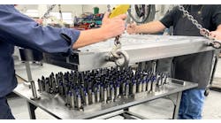
At one Midwestern foundry and pattern shop that specializes in aluminum and magnesium castings for aerospace components, refurbishing parts is a routine part of the business. GKS Global Services, a supplier of 3D laser scanning services, recently assisted in one of these refurbishing projects, providing scanning services to accelerate the project, to make inspections more accurate.
Now, refurbishing parts involves working from CAD models, but in the past the process was more labor-intensive. Castings were sprayed with blue dye and set on a layout table. Lines were scribed in the dye at specific heights while gages and instruments were used to measure dimensions and locations. These measurements were compared to 2D drawings and discrepancies were compiled as a report, to eliminate or to correct the differences from the original 2D drawings.
This process was also very time-consuming and expensive: it might take 10 weeks to complete one part, in addition to the idle production time that accrued. An average project could take up to 200 hours — at a cost of $50/ hour — costing almost $10,000 per project.
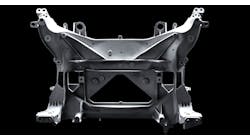
The project that GKS joined involved a 19-in. diameter casting with a gearbox in the center. It had been in production for 20-30 years, and the first CAD model had been made in 2008, although it had never been verified against the physical part. The model was created by inputting the dimensions manually from the 2D drawing.
GKS scanned both sides to capture all of the external 3D geometry. However, a complete capture of the internal cavity was not attempted because there was limited access to cored features. Instead, ultrasound was used to determine the thickness of the metal in the multiple cored passageways and gearbox.
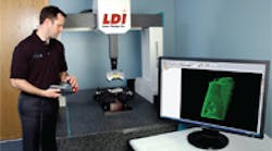
Next, GKS engineers laser scanned the original casting and the new casting made from the refurbished equipment in just two hours per part, using the Surveyor WS-2030 CMM, which is equipped with a Laser Design Inc. high-precision non-contact SLP-500 scanner. The non-contact 3D laser scanning is a complete measurement method, capturing all the surface objects, including free-form shapes and fine details. It also captured some internal features, such as the core entrance and exit from internal features, and the gearbox geometry. All this corroborated the other inspection techniques.
In 3D laser scanning, a line of laser light is projected onto a surface while cameras continuously triangulate the changing distance and profile of the laser line as it sweeps along. The laser line passes over the area until the complete surface is captured. All shapes are instantaneously replicated digitally on screen. Several scans are made to capture the entire part and then the point cloud of data files (the tens of thousands of points per second generated in each scan) is rotated into the same reference frame and assembled into an exact 360° representation of the scanned part.
There are no variations in practices or techniques among operators, because it is a noncontact measuring method. Laser scanning allows consistent capturing of the parts’ geometry by removing human error as a factor.
After this process GKS engineers compared the 2008 CAD model to the point cloud data to verify the part’s acceptability. Data from the old and new casting were overlaid to ID discrepant areas, identified by item number referencing the 2D drawing. Of over 700 possible items, less than 5% were out of tolerance. These items were compiled in a colorcoded inspection report. The laser scan also was used with inspection software to validate dimensions against the 2D drawing.
Since all the dimensions in the scan data are available in the inspection software program, the foundry’s engineers could easily work through the differences in each version and determine the correct ones. Verification will eliminate errors by going though assignable causes: were they caused in the after-cast process? Was it due to some gating left on the casting? Was the part over-benched, so too much material was ground-off, creating an undersized condition? Was it caused by warping when the molten metal cooled and the foundry used force to straighten the part?
The scan data showed that the physical parts were not identical to the CAD model and that the CAD model was not identical to the 2D drawing. However, once the 34 discrepant items were studied in more detail, there were only a few insignificant errors among them, none of which affected the part’s performance. Based on the scan data, the foundry’s engineers could be certain quickly that the new refurbished equipment met the criteria of the 2D drawing and the standards were acceptable to their customers.
The digital scans also helped the foundry’s engineers correct the 3D model so it matched all the dimensions of the drawing, so that future inspections will be fast and efficient. And, the new inspection process eliminated human error from the qualifying process.
