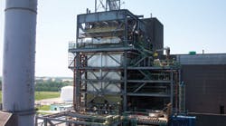
Design Considerations for Water Gauge, Flue Plate Stiffeners, and Insulation Systems
Hot flue with insulation applied by humping over each individual stiffener.
A close-up view of W12 and W14 stiffeners.
Soon, the federal government will impose the same air-pollution standards on metalcasting operations as it does now on the steam-generating industry, requiring installation of expensive pollution-control equipment. When designing your own insulation and lagging system, the stiffener pattern and size is the first thing you need to consider — and it is imperative to understand how the size, shape, and pattern of the external stiffeners are developed.
Most companies rely entirely on the expertise of OEMs or subcontractors when they are in the market for new equipment (furnaces, ladles, etc.), or rebuilding/relining existing equipment. You may think this is a sensible approach, but based on my plant visits, and having noted the insulation and lagging installations on the hot-exhaust flues, I assure you there is room for improvement after noticing insulation and lagging on their hot exhaust flues.
The Clean Skies Act, Clean Air Interstate Act, and the Mercury Rule have forced many power plants and municipal waste combustors to lower their NOx, SO2, and mercury emissions. This can be done either by building a new power plant to lower the overall emissions average of a company's power fleet; by adding low-NOx burners to their existing boilers; or by installing very expensive air-pollution control equipment such as selective catalytic reactors (SCR), selective non-catalytic reactors (SNCR), wet or dry scrubbers, precipitators, and baghouses. An average air-pollution control system added to an existing plant could cost over $100 million dollars and requires very extensively designed and well-conceived insulation and lagging systems to protect this very expensive capital improvement.
From my perspective, it is imperative that those working in this industry start to learn as much as possible about flue designs and the impact they have on getting a properly designed insulation and lagging system.
Basics of insulation and lagging
Insulation and lagging are important components of any air-pollution control system, representing almost 7% of the total construction cost. Improperly designed and/or installed insulation and lagging could have an adverse effect upon the equipment (i.e. corrosion at the flue substraight.)
In my experience, the OEMs that design the air-pollution control systems you may buy invest too little effort in the design of the insulation and lagging. Most of their equipment is designed to operate above 350°F, with stiffeners that are taller than 7 in. Stiffeners greater than 7 in. tall operating above 350°F are very difficult to insulate and lag because they almost always eliminate the possibility of burying the stiffeners with insulation, due to labor and material costs, and the insulation and lagging will almost always be installed outboard of the stiffeners, over the stiffener face.
Having the insulation and lagging installed over the outside face of the stiffeners raises important issues when the system is operating above 350°F. When the insulation is exposed to temperatures above 400°F, it causes the binder (mineral-wool type) to burn out. And, when the binder burn out occurs, the insulation must be supported as a sandwich construction (bottom and top) because the air-pollution control systems are prone to vibration. The vibration and binder burn out will cause the insulation to fall apart.
Design and impact
OEMs design their flues and air-pollution control equipment with very large stiffeners, taller than 7 in., and construct the system (or subcontract construction), including the insulation and lagging. They will almost always subcontract the insulation and lagging to an outside company, looking for the lowest bidder and shortest construction schedule. The cheaper that the insulation and lagging system is, the shorter will be the life expectancy and/or longevity of that system.
A properly designed insulation and lagging system may last 25-30 years, but typical systems in use today, in conjunction with the large stiffeners, probably will only last 10 years.
Along with the physical restrictions, there are other factors that will affect the design, such as the gas temperature and the water gauge. Of all the factors, the water gauge is the most important and least understood. The term refers to an instrument that indicates the level of water in a boiler, tank, reservoir, or stream. The gauge measures water depth in inches, and while that alone does not tell us enough it's a good place to start.
Stiffener size is based primarily on three factors — span, pressure, and temperature. The specific size of the stiffeners is limited by stress or deflection, so after a flue or duct system layout has been completed the stiffener size can be determined by considering
- internal static pressure of the contained fluid (ie., spent gas or air);
- transient pressure designated for the system (where we find reference to water gauge);
- deadweight of plate, stiffeners, insulation, lagging, etc.;
- wind and seismic loading;
- expansion joint actuation forces;
- ash accumulation (if applicable); and
- load transfer from other equipment.
All these forces must be taken into account in for flue or duct stiffener sizing, along with any and all governing codes.
Insulation thickness or insulation and lagging system requirements are important, but the development of flue stiffener sizing and spacing affects the insulation and lagging design. Using the above information, design engineers will be able to determine the size of the stiffener (see Equation No. 1 and Equation No. 2, below.)
This calculation allows the designers to consult references (1, 2) to find a suitable stiffener size.
There are two key elements in the formulas that affect insulation and lagging system design: stiffener spacing and water gauge.
Today's insulation systems
It used to be the case that calibrations considered insulation and lagging systems when determining stiffener sizing and spacing. As recently as 15 years ago, 17 in. was the norm for the water gauge pressure for a flue or casing system. Designers of flue work considered the insulation application because water-gauge pressure was half of what is required today. They understood that the higher the water-gauge figure, the larger will be the stiffeners will be, and the harder to insulate and lag.
Today, stiffeners designed for hot-flue or air-pollution control equipment (350°F and greater) are quite large and much farther apart; it is common to find stiffeners 12 in. or greater. It would be economically impossible to hump or bury the stiffeners, so placing insulation on the outside of the stiffeners is the only option.
One way is to use a 22-ga inner support plug welded to the stiffeners to support the insulation. Because this is expensive and time-consuming, other insulation systems are considered that in the past would not been used for a hot system (over 350°F), such as H-bars and pre-insulated lagging panels.
These are three of the most commonly used lagging attachment systems used now in the power industry, due to the large stiffener arrangements:
- The H-bar system is engineered and prefabricated off-site, then installed at the job site or at the flue fabricator's shop. Originally, this system was designed to be used for low temperature applications, 450°F and less. The H-bar support system is fabricated very much like continuous gutters and installed over the outside of the stiffeners. These H-looking steel channels (two C-channels, back to back) are attached to the external surface of the stiffeners, and form a "picture frame" in which the insulation sits. The height of the H-bar should equal the thickness of the insulation required. Then, the lagging would be attached directly to the H-bar frame.
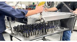
- Pre-insulated lagging panels are a pre-fabricated and pre-engineered system that is designed, fabricated, and installed at the job site or off site. Pre-insulated panels are fabricated from aluminum lagging, laid face down on a table in the shop. Insulation pins are welded to the lagging sheet on approximately 12-in. centers and impaled over the pins. Aluminum foil is placed over the insulation and a galvanized mesh (generally 22 5/8 in., 16 gauge) is placed over the foil. The mesh keeps the insulation in place and will help prevent the fibers from settling to the bottom. A 2.5 in. square speed clip is placed on the pins, which are bent over to hold the panel together. Then, this insulated lagging sheet or panel will attach directly to the outside of the stiffeners or to a subsystem made from angle iron.
- The inner support system uses a support system over the top of the external stiffeners that will support the insulation and lagging. One method would be to use a 22-gauge inner lagging material plug-welded to the external stiffeners. Then, the insulation and lagging would be installed with the lagging in direct contact with the insulation, thus creating support on top and bottom. The insulation and lagging will be attached to the inner support by a separate support system (pins, clips, Z clips, and or sub-girt).
Another method uses 66 road mesh or expanded metal in lieu of the 22-gauge inner lagging. The mesh or expanded metal has open areas that allow the insulation to vibrate away due to binder burn out.
Whether you are the designer or installer, the insulation and lagging system should be a primary consideration when designing a hot flue or air-pollution control equipment. To insulate an pollution-control system designed with a high water gauge, you will likely use a combination of one or more of these insulation and lagging systems. They should be used carefully, as they have very specific thermal expansion, material handling, and clearance issues that must be addressed in the project design stage.
If the external stiffeners are set at a maximum height of 7 in., then two layers of insulation (4 + 4 in.) could be used to bury the stiffeners and allow the insulation to be supported on top and bottom — assuming the lagging is installed in direct contact with the insulation. This would lower the overall cost (material and labor) but it is also the preferred method of insulating a hot system because:
- It eliminates potential heat transfer from the stiffener to the lagging surface.
- There are fewer thermal expansion issues because the expansion is taken up in the insulation attachments (pins) and lagging support system (Z clip, stud, sub-girt). These types of attachments have fewer expansion issues than a structurally supported system, like the H-bar or panel system.
- It is the most cost-effective (labor and material) to install.
- Clearance difficulties are minimized (stiffener height +1 in. over for the insulation +1.5 in. for the depth of the lagging).
- It minimizes the problems associated with binder burnout, because the insulation is sandwiched between the flue plate and the outer lagging.
Whether you are the system operator, designer, or installer, the insulation and lagging system should be a prime consideration in the design of stiffeners for flue and/or air-pollution equipment. It has been estimated that over the next five years the power-generating industry will spend over $35 million dollars to repair or replace insulation and lagging systems on installed flues and air-pollution control equipment, partly due to stiffener sizing and spacing, and the selection of insulation and lagging systems. A well-designed and -installed insulation and lagging system will save money and energy at a rate that is essential for an efficient plant operation.
Stiffener and Insulation Guidelines
- External stiffeners on any one rectangular surface should be of common height, as required to meet stiffener span designs.
- All external stiffener heights should be, wherever possible, no greater than 2 in. of the minimum insulation thickness up to a maximum stiffener height of 7 in.
- External stiffener spacing should be at 24, 36, or 48 in., wherever possible, to accommodate economical insulation applications.
- When the specified insulation thickness is within 2 in. of equaling the total stiffener height, the insulation thickness should be increased to at least 0.5 in., or more, to bury the stiffener.
- When the external stiffeners are spaced six feet or more apart, the insulation should be "humped" over these stiffeners.
- When the external stiffener height is greater than 7 in., a 22-gauge inner lagging should be used over the top of the external stiffeners to support the insulation.
