Previous entries in this series examined the roles iron oxide and free-oxygen atoms for cupola melting processes. Both of these are important factors for foundries seeking to maximize cupola operation. Assuming iron-oxide formation within the cupola has been addressed and countered, the next step for the operators is to make the changes necessary to maximize thermal efficiency of the cupola.
During the cupola’s melt cycle, coke is combusted to produce heat. Maximum heat generation happens in the tuyere raceway, or slightly above it. Because no oxygen is contained in blast air reaching below tuyere level, no coke combustion occurs there; hence no heat is produced below tuyere level. Therefore, all heat energy below the tuyere level must be transferred from the hot zone of the tuyere raceways.
Molten iron droplets descending through the hot zone provide the heat-transfer mechanism. Heat is robbed from the droplets throughout their descent to the bottom of the cupola, transferring heat to the coke and slag found there. Greater distance between tuyere level and the cupola bottom causes more coke and slag to be contacted by the molten droplets. This important cupola design detail -- i.e., tuyere elevation above the tap-hole -- will be discussed in further detail.
Heat energy supplied by coke is dependent on the amount of coke present. A given coke rate supplies a finite amount of heat energy. The cupola’s thermal efficiency determines how the available heat energy is divided between sensible heat to the molten iron and wasted heat to the cupola; exhaust gasses, slag, etc.
Retained-slag is a liquid and as such it transfers heat to the cupola shell and refractory much quicker than chunks of coke will do. The volume of retained-slag inside the cupola is basically unknown in most cupola operations. Evidence of liquid slag backing up and reaching tuyere level is commonplace. Typically, the tuyere level is nearly 40 inches above the tap-hole, a separation that results in large volumes of unwanted slag present inside operating cupolas.
Regulating hydraulic pressure. The volume of retained-slag inside the cupola is regulated by the hydraulic relationship created by the metal dam height versus the back-pressure inside the cupola pushing down on the slag layer, and the weight of slag pushing down on the molten iron reservoir created by the metal dam. The metal dam establishes the iron reservoir that must be pushed out the tap-hole before the lighter slag can escape the tap-hole. Restated, the force pushing on the molten metal reservoir is the pressure formed inside the cupola from the blast air and the weight of the slag on top of the molten metal.
Back-pressure within the furnace is not routinely measured on any cupola. However, when an extraordinary effort is made to do so, the pressure recorded is vastly different than the operating back-pressure recorded by the instrumentation provided by the cupola’s manufacturer. The normal back-pressures indicated include the blast-air resistance due to the confined design of the tuyeres, tuyere pipes, wind box, etc.
The true blast pressure inside the cupola is seldom measured but end up at a startling 10% of the cupola’s indicated back-pressure. Cupola operators have been misled for years by the erroneous pressure readings.
Most cupolas contain “safety tuyeres,” which are drain ports, whereby blast pressure is sealed off by thin aluminum plates; designed to melt instantly and open to metal flow if liquid iron rises to the level at which those plates are installed. Typically, safety-tuyeres are installed approximately 14-17 inches below the water-cooled tuyere level.
Cupola designs do not allow easy measurement of internal pressure created by blast air. Cupola manufacturers must change that and incorporate simple pressure ports, which will ensure precise pressure within the cupola and facilitate accurate adjustment of metal dam heights.
Optimizing metal flow. One method used to determine internal operating back-pressure is to install a pressure gauge through the aluminum “burn-out” plate in the safety-tuyere. A problem encountered on most cupolas with this technique is the safety-tuyere quickly plugs with slag during melt start-up, so only a quick glimpse of internal pressure is obtained. But the back-pressure obtained during bed burn-through, prior to melting, can be obtained and compared to the “normal” back-pressure reading. Thus, the relationship between actual back-pressure within the cupola and the cupola’s “normal” back-pressure can be established.
Slag produced during the melt cycle accumulates within the cupola according to the hydraulic relationship; the “metal dam height” produces roughly five ounces per inch of dam height and is offset by the internal back-pressure created by blast air and slag weight on the molten metal.
Heat-energy losses to retained-slag are a major portion of all thermal losses. Yet, few cupola operations are concerned with high-retained-slag levels. This must change. Operators’ concern must be raised, to minimize retained-slag volume inside cupolas.
Actual internal back-pressures indicate 2-8 ounce maximum pressure exists. More measurements are needed to establish typical pressures. But five ounces of back-pressure offsets one inch of metal dam. Most cupolas operate with excessive metal dam heights, producing the near-tuyere-level retained-slag conditions that hamper cupola melting today.
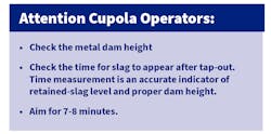
Cupola operators take note: check the height of the metal dam in your furnace -- and check the time for slag to appear after tap-out. Time is an accurate indicator of the retained-slag level (aim for 7-8 minutes) and the proper dam height.Managing slag volumes. After cupola tap-out, molten metal extends back into the cupola and establishes its height above the tap-hole, in relation to the metal dam height. The hydraulic balance previously discussed comes into effect. Slag cannot exit the tap-hole until the hydraulic balance is overcome.
Following tap-out, slag continues to build up inside the cupola until all molten iron is forced out of the cupola. At that point, the lower-density slag flows out the tap-hole and steady-state retained-slag levels are achieved.
The time elapsed for slag to flow after tap-out serves as a good indicator of the retained-slag level inside the cupola, and the need for reduced metal dam height. Many cupolas do not begin slagging for an hour or more. Simple calculations will indicate the slag volume inside the cupola. Cupola operators should realize that slag volume is robbing heat from melting iron.
Many unwanted slag / metal chemical reactions occur in the retained-slag layer. A large volume of retained-slag promotes long contact time that the molten droplet endures during its downward travel. Concerning lime removing silicon from molten iron, in one instance a two-inch reduction in metal dam significantly reduced silicon loss.
Cupolas with proper metal dam height should allow slag to flow out the tap-hole within 10 minutes.
Retained-slag levels dictate the heat loss / heat robbed from the metal droplets. The descending molten-metal droplets continuously heat all slag retained inside the cupola. Minor reductions in the retained-slag level inside cupolas have produced 75°F and more metal temperature increases. Cupolas operate effectively with 2- to 3-in. metal dams.
Adjusting cupola pressure. Later this year, Mastermelt will introduce a moveable metal dam design for cupola front boxes, designed to rise and fall as the internal back-pressure fluctuates. This device cannot be utilized until slag chemistry is perfected to eliminate iron oxide. A free flowing, non-sticky, non-crusty slag must exist so that the moveable dam refractories can slide on themselves without tearing up the contacting surfaces. That type of cupola slag is being produced in de-oxidized cupola operations today, but this is not a well-known process. Still, it is a critical aspect of the new, moveable metal dam technology.
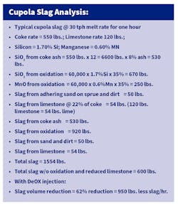
Slag produced during normal cupola melt cycles results from melted coke ash/residue, melted adhering sand and dirt, by-products of oxidation reactions occurring inside the cupola, and melted lime. Coke ash is primarily silica, SiO2, and it amounts to approximately 8% of the coke weight.
Oxidation by-products contained in the slag are primarily SiO2 and MnO. Many cupolas operate with 35% silicon/manganese oxidation loss. Lime is added to reduce the composite slag chemistry’s melting temperature. With de-oxidation, less silica is contained within the slag, making it possible to reduce the volume of lime addition.Cupola thermal efficiency. To review:
1) Coke rate determines heat available for melting and superheating iron.
2) Metal dam height determines volume of slag retained inside the cupola.
3) Determine metal dam height using actual operating data from the cupola.
4) All material, coke and retained-slag, below tuyere level is heated by robbing heat from metal droplets.
5) Retained-slag should be minimized.
6) Mastermelt DeOX Metal Treatment reduces slag produced during cupola melt cycle by 62% or more.
In articles to follow in this series, slag generation in EFs and cupolas will be more thoroughly reviewed. Cupola design factors affecting thermal efficiency will continue to be examined. Tuyere height above the tap-hole, a very critical cupola design parameter, will be thoroughly reviewed.
In the end, an optimum cupola operation and optimum cupola operating technique will be presented.
Ron Beyerstedt is the president of Mastermelt LLC. Contact him at [email protected]
This is the third in a series of reports examining cupola design, cupola melting practice, and cupola technology solutions. Also see:
Maximizing Cupola Performance, FM&T March 2021.
Controlling Conditions for Cupola Melting, FM&T April 2021.
About the Author
Ron Beyerstedt
Ron Beyerstedt is the president of Mastermelt LLC. Contact him at [email protected]


