Robotic Core Setting for Permanent Mold Casting
Robotic sand core setting into a mold has the potential to increase molding productivity and reduce casting scrap.
With the evolution of casting designs, driven by requirements for lower-weight parts and (in automotive applications) a desire to minimize assemblies, there follow designs with thinner walls and smaller openings/cavities. These structures need cores to create those thin wall sections, and in some examples these walls are as thin as 4 mm. In addition, small cores are used to create small openings and cavities.
But, small cores are fragile and prone to crack, and when they do crack the result is a scrap casting. Usually, that scrap is not detected until the finishing stage, or under X-ray analysis, and sometimes it’s not discovered at all.
Scrap reduces profitability, and so for foundries that produce thin-wall castings to achieve competitiveness, the core handling and setting process must be gentle and repeatable.
Obviously, good cores are the starting point. Proper resin levels, adequate definning, and accurate assembly are the foundation of that effort. Transporting these cores and core assemblies to the molding machine without breaking them is the next critical step. The final step is setting the core into the mold.
Setting the core in the mold -- specifically into a permanent mold -- can be a delicate procedure. Done manually, there is potential to cause damage to the core and leave loose sand inside the mold. Further, the machine operator is at risk of burns, crush injuries, back strains, and carpal tunnel syndrome in the wrist thanks to the strain of repetitive awkward motions required to place the core properly. Automating this core setting operation with a six-axis, foundry-hardened robot (which will replicate the movements of an operator), addresses the issues of core damage during setting and sand inclusion, as well as removes the operator from the hazards mentioned above.
Design in Progress
Rimrock Corp. was tasked with setting cores for a high-volume casting involving a horizontally parted permanent mold. The cores were cold-box products and had some thin, 12-mm round sections. The mold had two cavities and was mounted in a tilt-casting machine. There were eight machines on the turntable, which indexed every 40 seconds.
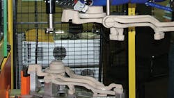
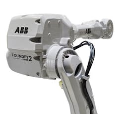
Adding to the difficulty of this arrangement, gripping the core was a very specific challenge. The EOAT — end-of-arm tool, or end effector, which is a device distinct from the robot and selected with specific application to the automation task — was mounted on an ABB IRB 4600 Foundry Plus robot. The tool utilized a rubber “squash” ring to expand inside a hole in the core and a parallel gripper to contain the long tail section of the core without actually gripping it. For this automation effort, the core had been specially designed with a hole to accommodate the EOAT’s grip.
Core setting into permanent mold machines that are mounted on a turntable is especially difficult because the turntable does not always stop in the same location in front of the robot. Depending on the machine’s location with respect to the “ideal” location on the turntable, the location of the each mold in relation to the robot may be different.
The location delta from “perfect” to actual will change whenever a machine is removed and replaced on the turntable, or whenever the mold is removed and replaced in the machine.
Enhancing the Sequence
The foundry started its effort to minimize damage to its delicate cores in the core room, and used individual core assembly/gluing fixtures made from cast aluminum. Then, these fixtures were placed on core racks and transported to the mold line by forklift.
At this point, Rimrock incorporated a series of features into the remaining steps of the foundry’s core-setting sequence:
1. An encoder was mounted on the turntable rotation shaft to indicate to the robot where the turntable stops. Based on theencoder count, the robot would know which casting machine is in front of it, and its approximate location. Knowing which machine is in front of the robot allows the robot programmer to teach specific positions based on the uniqueness of that particular machine, if required.
2. Two laser distance-measuring sensors were incorporated to the design of the robot’s EOAT. Knowing the approximate location and the machine number that is in front of the robot meant that the robot would be able to move to a close starting position, and then to use the lasers to measure the “X” location and angle (about the “Z” axis) of the mold.
3. An XY compliance device along with alignment features on the EOAT provided the final position compensation required to achieve precise alignment with the mold. The two alignment features were mounted on Z floating slides, and were mounted lower than the core on the EOAT. The details engaged the mold sooner than the core did during the Z downward movement into the mold, and the XY compliance device allowed the EOAT to float with respect to the robot.
Compliance (aka “flex”) inherent in the robot’s design provided the float needed to accommodate any rotational differences between the EOAT and the mold, so that the core entered the mold cavity in the correct XY location and orientation.
These same alignment features were used to align the EOAT with the core assembly fixture at the point of pickup from the core in-feed turntable to the robot cell.
4. The core was released approximately 1/8-inch above the final location in the mold to allow it to seat gently in the mold.
5. Finally, an air knife was used to blow any loose sand out the mold. This blowing step is done prior to and after loading the core into the mold.
Tracking Core Setting
The core setting operation is as follows:
1. The operator removes a fixture holding an assembled core from the rack and set it on a small in-feed turntable outside the robotic cell. The operator repeats this for a second fixture.
2. Next, the operator activates the turntable and it rotates the fixtures/cores into the robotic cell.
3. The robot moves to the turntable and picks a core out of the fixture with its EOAT.
4. Then, the robot moves the core to a sensor array to ascertain that the core is present. If a problem is found, the robot deposits the core in a scrap bin.
5. The robot moves to the open mold and starts its search routine using the encoder data from the turntable.
6. The robot moves to the mold and finds its exact location with two laser sensors.
7. Then, the robot sets the core into the mold using the alignment and compliant features of the EOAT.
8. The EOAT releases the core just before it contacts the mold. This is done so that the robot does not drive the core into the mold, which could break the core and/or damage the mold.
9. The robot returns to the infeed turntable, picks up a second core, and sets it in the mold as described. However, the robot skips steps 5 and 6 for this second core placement because the mold location has been determined already and stored in the robot.
When this concept was demonstrated for an exhibit, no real mold was available: a fixture was made to receive the core, so that one could manually move its position. The robot successfully set the same core hundreds of times in the fixture without breaking it.
Sand cores can be robotically set into molds of all kinds. The critical factor is to account for all the design details of the core throughout the manufacturing process — production, assembly, storage, handling and transport, and finally setting the core. With proper planning and design considerations, which may start with at initial core design, a robot can set cores successfully. And, that success can increase molding line productivity, reduce casting scrap, and reduce workplace injuries.
Mark Riekert ([email protected]) is the manager of application engineering and project management, and John Kuhn ([email protected]) is a foundry automation specialist. Both are affiliated with Rimrock Corp. Visit www.rimrock.com

