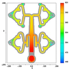
FLOW SCIENCE INC. recently delivered version 11 of its FLOW-3D CFD software for analyzing physical flow processes, including mold-filling simulation, one of the most widely used programs for simulating metalcasting processes. The developer reported a number of highlights in the new version, starting with a new visualization tool called FlowSight™, as well as advanced meshing capabilities.
FlowSight is based on the EnSight® post-processor and offers users new ways to analyze, visualize, and communicate their simulation data.
“The extensive work that we’ve done to customize EnSight … to display the complex flow regimes our customers use FLOW-3D to understand is only the beginning. From here on, FLOW-3D users will be able to take their analysis to another level,” according to Flow Science president Tom Jensen. “Coupled with further development of cutting-edge models in the FLOW-3D solver, version 11 is definitely a major step forward and we are eager to see our customers’ reaction.”
The new release also brings increased meshing capabilities, including conformed and partially-overlapping meshes, and “solution sub-domains” that decrease significantly the memory requirements, simulation times, and size of results files without compromising accuracy.
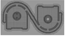
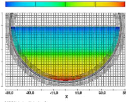
The improvements to meshing functions include the new availability of “conforming mesh blocks”: Instead of being rectangular, as all standard mesh blocks are, conforming mesh blocks are shaped according to the geometry. There may be two types – cavity-conforming and solid-component-conforming. A cavity-conforming mesh block is commonly used in casting modeling, where the cavity typically requires a finer mesh than the mold. The simplest setup is to have one rectangular mesh block with a relatively coarse mesh covering the whole domain and a nested cavity-conforming mesh block around the cavity.
A component-conforming mesh block is useful when resolving thin structures or thin boundary layers around solid structures. The user can select which component(s) a mesh block should conform to. By default, conforms to all solid components within its rectangular volume.
The extent of a conforming mesh block beyond the boundaries of the shape it is conforming to is defined by the input parameter overlap. By default, it is equal to five times the average cell size in the conforming mesh block. Conforming mesh blocks can be nested, linked, partially-overlapping or simply standalone mesh blocks.
In addition, v.11 does not require mesh blocks to be simply linked or nested. Mesh blocks can overlap each other in an arbitrary fashion. In areas common to several blocks, the flow equations are solved in the one with the finest mesh (based on the average cell size in the block); the solution is interpolated in all the other blocks. The user can override this order by setting the mesh block ranking.
When a nested block's boundary coincides with an external boundary of the containing block, the user can define the standard boundary conditions at that nested block's boundary, independently of those of the containing block. Previously, a nested block always assumed the boundary conditions of the containing block.
Extending Memory Allocation
Regarding solution sub-domains, the developer explained that FLOW-3D v.11 extends its “Unstructured Memory Allocation” approach to addressing solution arrays on structured grids so that it uses separate memory space (sub-domains) for different numerical solutions, specifically a) fluid flow, b) heat transfer in solid, and c) core-gas flow. A solution variable is stored only in cells where it is needed. The result is a much more compact and efficient representation of the solution in memory (e.g., no fluid variables are stored in fully solid cells and vice versa), shorter simulation times (due to addressing a smaller memory footprint) and smaller flsgrf files (because of writing out smaller datasets). No input is required from the user to take advantage of this development; the creation of the sub-domains happens automatically based on the geometry and model selection. There is also no loss of solution accuracy.
In addition to these improvements, FLOW-3D v.11 includes a more accurate core gas model and an improved surface tension model. The accuracy of the core gas model is enhanced by the introduction of the core gas solution sub-domain, which includes not only the fully blocked cells of a core gas component (as in previous versions,) but also the partially blocked ones. Also, the core gas model has been SMP parallelized.
In diecasting simulation, core and liners are inserted into a die assembly and are removed after each cycle. This can be modeled by defining special types of components. Unlike other parts of the die that are reused after each cycle and thus retain their temperature history, the temperature of cores and liners is reset at the beginning of each cycle.
The cooling channel model is made more versatile because it is completely separated from the void model, which previously was used to define cooling channels. Cells occupied by a cooling channel are still empty of solid and fluid material, but they are not included in the calculation of void regions.
As a result, the reported void regions represent the actual physical voids in the problem. Also, a cooling channel can be connected to a void region and still retain its properties and functionality as a cooling channel. When cooling channels are defined with STL files, those STL objects can be loaded in the 3D viewer and manipulated (e.g., hidden or made transparent) independently of the rest of the geometry.
FLOW-3D v.11 adopts a new surface tension model that the developer noted has demonstrated better accuracy and stability of the solution. In particular, the accuracy of the calculation of wall adhesion forces is greatly improved. The old surface tension model is still available — activated by adding IFSFT_OLD=1 to the namelist XPUT.
Visit www.flow3d.com


