The correct design of gating and risering is essential for a foundry to be successful in the production of high-quality castings. As customers demand that the lead-time for new parts be as short as possible, foundries that can produce sound castings from the very start have a distinct advantage: A proper rigging system design is the critical element to making this happen.
Designing efficient gating and risering systems is difficult for foundry engineers because of a number of common factors. Chief among these is the complex geometry of many commercial castings; while there have been well-established design rules for a number of years, the application of these rules to a variety of commercial casting shapes typically involves cumbersome calculations that, when performed manually, require a number of simplifications, i.e., approximations, to accommodate the reality of design and manufacturing conditions.
These approximations can reduce the accuracy of the resulting designs. Even when rigging calculation methods are used, if the work is not integrated with a simulation tool extra effort will be needed to perform the calculations. Also, the data used in the integration will not be nearly accurate as simulation results themselves, which take into account such things as the casting alloy, molding materials, and the like.
With the advent of simulation programs, it is possible to synthesize the elements of good rigging design into a general method that is fast, thorough and highly accurate. This overcomes many of the difficulties listed above. In addition, because of the automation involved, this method allows foundry programmers and operators who may have limited experience (e.g., new foundry engineers) to design casting rigging effectively. Many foundries have encountered serious problems when experienced designers retired from the workforce; an automated design methodology lessens this impact.
The general design process consists of five steps: Simulation of the ‘naked’ casting; Riser design; Gating system design; Rigging geometry creation; Verification via CFD/solidification simulation. Following here is a detailed look at this process, using a commercial ductile iron casting.
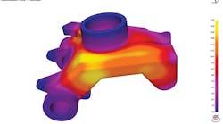
“Naked” simulation — The first step in the rigging process is to run a simulation of the part ‘naked’, that is, without any rigging system. Simulation results show the effects of the part geometry on the overall solidification. In this initial simulation, filling analysis typically is not done, which allows extremely rapid results and can point out preferred gate and riser locations, which would promote directional solidification.
All that is required for the initial simulation is a casting model, normally provided by the customer in STL file format, and basic process details such as casting alloy, mold material, and pouring temperature.
Riser design — Once the initial simulation is complete, the data from the simulation can be used to design the rigging components. Typically the risers are designed first, followed by the gating system.
For shrinking alloys, the software uses the progression of solidification, along with a pattern recognition algorithm, to determine the separate feeding paths on the casting. Further, the software can locate the last points to freeze on each feeding path, which will be the preferred riser contact points.
For gray and ductile irons, the software does additional feeding zone analysis based on the German VDG diagram, which predicts when graphite expansion will take place in the casting. Each feeding zone identified requires one, and only one, riser, as shown in Figure 2.
Feeder sizes for each feeding zone are calculated by the software using variations on the well-known Modulus Technique. Solidification time information from the initial simulation is converted into a ‘thermal modulus.’ This takes into account not only casting alloy and mold material, but also the solidification dynamics of the specific mold situation. Feeding aids, such as insulating or exothermic sleeves, can be accommodated in the calculation. (Figure 3.)
Gating system design — After all risers have been calculated, the next stage is to design the gating system, to bring the metal into the mold efficiently. Calculations are based on both Bernoulli’s Theorem and the Law of Continuity. All components of the gating system are calculated, including sprue, runners, gates, etc. A sample screen from one stage in the gating calculation is shown in Figure 4.
Modeling gating, risering — Gating and riser calculations, as outlined above, will normally take only a few minutes to perform. The output is a spreadsheet of component dimensions that can be used to create geometry in a CAD system, or in the software model builder itself.
Many gating and riser components are used on many different castings in a given foundry. For example, a foundry may have a series of standard sizes of downsprues, or use specific sizes of riser sleeves. These types of components can be created once in CAD, then saved and reused in any model in the future, without having to re-create the geometry each time. If a library of gating components is developed and used, the entire gating and riser design process, from loading the unrigged model to having a fully rigged geometry ready for verification simulation, can be as short as 30 minutes or so. Figure 5 shows the fully rigged design, incorporating two castings, as well as a filter in the gating system.
Design verification using CFD, solidification analysis — Once the rigging system is in place, a full Computational Fluid Dynamics (CFD) analysis is performed to accurately predict and visualize mold filling. This also provides the most accurate temperature distribution in the casting and mold, which, in turn, provides a better solidification analysis.
In addition to temperature analysis, CFD can provide velocity information. It is important to keep metal stream velocities low during filling, to minimize chances for splashing, mold erosion and re-oxidation defects.
Filling analysis is automatically followed by solidification analysis, using a combined thermal and volumetric calculation. This technique not only predicts poor directional solidification; it also provides the most accurate analysis of macro-shrinkage due to volumetric feeding from the risers.
Figure 6 shows the progression of solidification and Figure 7 shows volumetric feeding of the risers. The ‘piping’ of the risers is displayed by plotting where the metal has lost density due to volumetric feeding. This rigging design produces a perfectly sound casting.
In many cases, the design portion of the analysis can be done in an hour or less. Typically, verification simulations, using full CFD analysis, can be done in about two hours or overnight. Simulation times will vary depending upon such things as computer processor speed and available memory, casting complexity and materials cast. In general, thinner walled castings require more computation time, and materials with higher thermal conductivities, such as aluminum and copper, also will take longer to simulate, all things being equal.
Simulation software has evolved from a problem detection/verification tool to an integrated part of the design process. Simulation is no longer used to check a gating and risering system, but to actually be the driving force for the rigging design. Even complex geometries can be successfully rigged in a short period of time using such tools.
Using simulation results directly in the rigging process produces a more accurate result than manual techniques, in a much shorter time period. This integrated approach reduces overall costs and lead times.
David Schmidt is the vice president of Finite Solutions Inc., a developer of casting simulation process technology used in over 800 foundries and universities worldwide, including the SOLIDCast, FLOWCast and OPTICast programs. Contact him at [email protected], or learn more at https://finite.solutions


