In iron and steelmaking processes, engineering design and the lining materials chosen are critical factors in controlling the efficiency and energy usage of the production equipment. As a result, it is critical that industrial designers understand the advantages and disadvantages of the materials they choose. For example, it is especially important to select insulating firebricks (IFBs) that minimize energy losses. Recent studies conducted on IFBs produced using the three most common manufacturing methods – cast, slinger, and extrusion – show that the cast process offers the lowest thermal conductivity and provides the greatest energy savings.
IFBs are highly versatile, and used variously in iron and steel production, including blast furnace stoves, ductwork in direct reduction units and reheat furnaces, back-up insulation in coke ovens, and in tundishes and ladles. They also are used to form sidewalls, roofs and hearths for heat-treating and coating lines.
IFBs are manufactured in various ways too, the most common of which are casting, slinger, and extrusion. The casting process uses gypsum plaster as a rapid setting medium for a high water-content clay mix, containing additional burnout additives. The slinger process is a form of low-pressure extrusion of a wet clay mix containing high levels of burnout additives, with an additional processing step in which the semi-extruded material gets ‘slung’ onto a continuous belt to generate additional porosity, before drying and firing. The extrusion process forces a damp clay mixture containing burnout additives through an extrusion nozzle, and the extruded material is cut into bricks, dried and fired.
The brick chemistries and microstructures produced may vary widely among these methods, leading to different thermal conductivities within products of the same temperature rating. This variation in turn has an effect on the ability of different IFB types to control energy loss.
To understand the effect of the three main IFB manufacturing methods on thermal conductivity and energy loss behavior, researchers conducted a study to quantify the differences in energy usage that can be achieved within Class 23 and Class 26 IFBs.
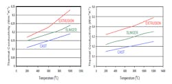
Two graphs show the thermal conductivity of the IFBs tested, a critical property because IFBs are primarily used for their insulating abilities. In each class of IFB, cast brick has the lowest thermal conductivity, followed by the slinger-produced brick, with the extruded brick displaying the highest conductivity.
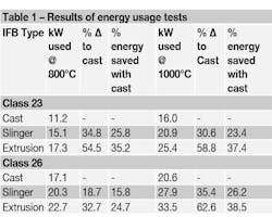
Researchers designed two identical electrically heated laboratory muffle kilns and conducted energy usage studies comparing among the IFB bricks. They lined the first kiln with Class 23 cast IFBs and this formed the benchmark, since they had the lowest thermal conductivity in the class. Test results are shown in Table 1.
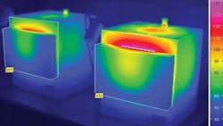
The thermograph image shown above shows the kilns during the 1,000°C firing test; the cast IFB lined kiln is on the left. It shows how much heat is wasted through the body of the kiln lined with the higher thermal conductivity IFB and how the surface temperature of the kiln becomes overheated. This shows both the effect of wasting energy costs and health and safety issues caused by hazardous working temperatures.
Significantly less energy was needed to run the test kiln through a 1,000°C firing cycle with the cast IFB compared to the extrusion IFB (37% less for Class 23 and 38.5% less for Class 26.) These energy usage differences are due to the differing thermal conductivities of the IFBs. In materials of similar chemistry, thermal conductivity is controlled by the structure of the material. The different manufacturing methods of the IFBs studied produce materials with inherently different macro- and microstructures and it is these that control the thermal behavior of the products. The texture of the IFBs is finest for the cast product and is coarsest for the extruded product.
Energy Saving Calculations
After conducting laboratory tests demonstrating the potential to minimize energy usage through appropriate selection of IFB for an installation lining, researchers ran heat-flow calculations to understand the effect on actual industrial installations. Calculations were done to assess energy running costs in strategic locations of two annealing applications that use IFBs as the lining material: a catenary strip annealing furnace and a cast iron part annealing furnace.
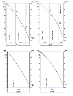
The modeling was performed using the most common, real-life IFB lining arrangements, where walls are normally built up using standard brick sizes, while roofs are constructed from special pre-assembled roof blocks. The results are shown in the series of four graphs: The top graphs show heat flow calculations for the catenary strip annealing furnace wall using cast IFB (left) and extrusion IFB (right). The bottom shows heat flow calculations for the cast iron part annealing furnace roof using cast IFB (left) and extrusion IFB (right).
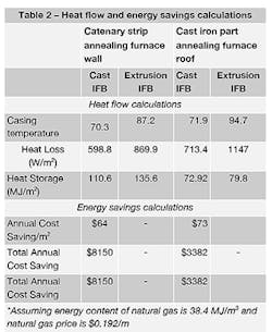
Table 2 shows the significant differences that can be achieved for casing temperatures when using different IFB types. Using cast IFB produces much lower casing temperatures than with extruded IFB. The lower surface temperature obtained using the cast IFB also produces a more comfortable working environment for operators and minimizes the risk of burns due to operators coming into contact with the surface of the installation.
The heat-flow calculations show that for the catenary strip annealing furnace wall, the lining with the extrusion IFB requires 271 W/m2 more energy to maintain the 1,200°C operating temperature than the lining with the cast IFB, due to the lower thermal conductivity of the cast compared to the extruded IFB.
The difference in energy consumption between the two simulated furnace walls equates to a saving of 42,450 m3 of natural gas per year using the cast IFB compared to the extrusion IFB. Assuming a gas price of $0.192/m3, this equates to an annual saving of $8,150/year for this wall section only. Assuming a furnace wall lining life of 10 years, the total saving over the life of the kiln lining would be $81,500.
The savings on the complete structure would be significantly larger. A 127-m2 working area in the wall of the catenary strip annealing furnace would need approximately 7,200 standard-sized IFBs. Although the cast IFB price is a little higher, the example shows an initial payback period of just over three months; for the rest of the 10-year service life there would be continuous cost savings due to the lower energy requirements.
For the cast iron part annealing furnace roof, the lining with the extrusion IFB requires 434 W/m2 more energy to maintain the 930°C operating temperature than the lining with the cast IFB.
For the 46.5 m2 working area, the difference in energy consumption between the two simulated furnace roofs equates to a saving of 17,615 m3 of natural gas per year using the cast IFB compared to the extrusion IFB, which equates to an annual saving of $3,382 per year for just this small roof section. Assuming a furnace roof lining life of 10 years, the total saving over the life of the kiln lining would be $33,820. The savings on the complete structure would be significantly higher. The 46.5 m2 roof area would need approximately 2,600 standard sized IFBs, so the payback for using cast IFB is less than 3 months.
By monitoring energy usage in laboratory kilns lined with IFBs manufactured by different process routes, and by modeling the effects on heat flow of using IFBs manufactured by different processes in two important iron and steel applications, research has demonstrated that IFBs manufactured by the cast process offer the lowest thermal conductivity available at application temperatures, and provide the greatest energy savings.
Steve Chernack is the manager of engineering accounts for Morgan Thermal Ceramics, a designer and manufacturer of heat insulation products for numerous industrial processes.
