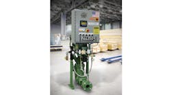
Foundries have a variety of methods for distributing sand throughout a plant or operations, commonly using belts, air slides, elevators, and pneumatic transporters. Pneumatic transporters tend to be the most popular due to their flexibility, reliability and dust containment characteristics.
Belt conveyors, air slides, and elevators are used frequently to distribute the sand but pneumatic transporters are probably the most widely adopted method for moving sand around the foundry. Pneumatic transporters are practical because of their simplicity and flexibility; however, because of their operating characteristics certain design and operating details should be followed to achieve a reliable system with minimum cost of operation.
Dilute- and dense-phase conveying
Pneumatic sand-transporting systems generally fall either into two types, dilute-phase conveying or dense-phase conveying.
• Dilute phase conveying is mostly used for powdery materials such as iron oxide and bentonite. It operates by vacuum or low-pressure air, with high velocities (4,000 FPM and higher.)
• Dense-phase conveying works by medium to higher pressure air and lower velocities (2,800-4,000 FPM.) For sand, which can become very abrasive at higher velocities, special low-velocity systems (400- 1,500 FPM) can be designed, and these should be used exclusively.
Ahead of making a choice, one must establish important system definitions. These are:
– Sand type and particle size AFS number.
– Bulk density (pounds per cubic foot.)
– Temperature.
– Moisture content.
– Dust and foreign matter content.
– Flowability / free flowing.
– The required capacity (tons/hour.)
– The location of the transporter blow tank; number and location of receiving bins (and if high level probes are to be present); location of dust collection (if present); compressed-air location and the shortest distance of horizontal and vertical connecting pipe sections.
– The length of pipe run (ft.)
– Identify individual pipe sections for horizontal and vertical pipe sections – H1, H2, H3, etc.; V1, V2, V3 etc. – where each straight pipe section is identified separately, such as H1 being the first horizontal section from the transporter discharge flange, and H2 the next horizontal section, normally some elevation above H1. Similarly, V1 is identified as the first vertical section, etc.
– The total number of pipe bends, all with a long centerline radius of 40 inches: 90° bends, 60° bends, 45° bends, 30° bends.
– For standard design, a pipe run of the shortest practical distance between the transporter blow tank and the receiving point(s), using the standard degree bends noted here is ideal and best practice.
Then, the developed length of the pipe run for the system is calculated by adding all horizontal and vertical sections and pipe bends, and assigning resistance to the system configuration. The final developed length of the pipe run can be used to arrive at the capacity of the system, based on the pipe diameter.
Compressed-air sand conveyance
To overcome the problems of abrasion when conveying sand pneumatically it has been common practice to use large, compressed-air conveyance systems like those commonly found in dense-phase conveying. Blow tanks for these dense-phase systems normally are increased in size to match the required tonnage rates.
All of these large vessel dilute-phase transporter systems, however, have a relatively large number of components that are subject to wear. Also, to reduce cycling frequency of affected components and increase their life expectancy, the largest blow tank for a given capacity is normally specified with an average fill time of 90 seconds or more.
To reduce operating costs of pneumatic transporters, smaller blow tanks with faster fill times (14 seconds or less) have been found to be less expensive to build and require less floor space. When all of the small efficiencies are incorporated into the PlugFlo method, they favor lower compressed-air consumption (of up to 45%) and use of more cost-effective, Schedule 40 pipe.
To eliminate pipe movement during operations, use solidly anchored pipe supports. Pipe and bend connections should use special-bolted flanged arrangements, eliminating any gaps between pipe ends and never use butt-welded, pipe-to-pipe connections.
After installation, the pipe run must be pressure-tested to verify that there are no leaks.
Only trained professionals should manage installation and startup. Adjustments to the air volume and pressure, if required, should be made with a clear understanding of the possible results and capacity of the system. Incorrectly changing of these settings on dense-phase systems can turn the system into a dilute-phase process – in which all advantages discussed here are lost.
Jim Gauldin is Chief Sales Engineer with Klein Palmer Inc.
