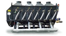
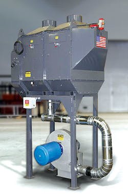
Many foundry managers and operators wonder about the possibility and/or effectiveness of removing airborne sand fines by using a fluid bed classifier. The following summary will help anyone to troubleshoot the sand classification process to increase fines removal.
Removing sand fines through the classifier depends on several process details, namely 1) dwell time; 2) fluidizing air volume; and 3) exhaust negative pressure in the head space.
Dwell time — The sand in a fluid-bed system resembles any liquid in a vessel. The faster that fluid is poured into the vessel, the faster the fluid will overflow. The dwell time in a fluid-bed classifier is determined by the rate that sand flows into the classifier. The inlet sand opening – butterfly or slidegate – regulates the flow of sand into the classifier.
It is necessary to set the butterfly or slidegate to regulate the sand flow, and the best way to set this is to keep the blower from starting. Then, gain access to the sand inlet and make sure that all sand processing devices between the sand control valve are empty – screener and magnetic separators.
Place the unit on manual and turn on the magnetic separator and the screener (if present.) After all of the sand has drained out of the screener, magnetic separator, and pipe, place one end of a chute under the sand inlet pipe and the other end in a tared container.
The container should hold 60 seconds of sand flow. Open the sand control device for 60 seconds as the sand flows into the container. There is going to be a delay, so wait until sand ceases to flow. For example, you should have a flow rate of 333 lb/minute for 10 tons per hour (333 lb/minute x 60 minutes = 19,980 lb/hr.) If the desired flow rate is not correct, it is necessary to adjust the sand control device and then retest.
An alternative to measuring the sand flow through the sand flow control device may be to multiply the number of transporter loads exiting the classifier in an hour by the capacity of the transporter. This does require that the sand flow has been continuous during the one hour; it cannot be stopped due to sand temperature exceeding limits, receiver silo full indicators stopping the system, or low sand volume in the supply silo.
Once the inlet valve is set to the designated sand flow rate, the sand is in the classifier for the designated amount of dwell time. The average dwell time will be the amount your classifier holds, e.g., 20,000 lb/h. The dwell time for a 7,160 lb capacity classifier will be 7160/20,000 lb/h = 0.358 hours or 21.5 minutes (it will not be less than this.)
If the classifier is also a sand heater or sand cooler and the sand temperature is beyond the heating or cooling range of the classifier at the set flow rate, the sand control device is programmed to close giving the sand more time to heat or cool. This increases the dwell time, which is likely to increase the fines removal.
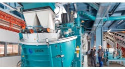
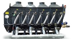
Generally, classifiers have 4-ft.-high expansion chambers immediately above the classifier exhaust connections. The diameter of these chambers is sized to reduce the exhaust air to a velocity of approximately 750 feet per minute, allowing the coarser sand grains to drop back into the classifier.
Anything that reduces the flow of sand into the classifier while it is running increases the dwell time and increases the removal of fines.
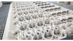
Fluidizing air volume — The design element that controls the volume of fluidizing air is the open area of the blower inlet blast gate. Plugged filters on the blower inlet also will reduce the fluidizing air. Individual blast gates below individual modules can redirect the flow of fluidizing air, or stop it completely if totally closed. Once the classifier is filled with sand and the filters are clean, the inlet blast gate usually is adjusted until the sand is bubbling about 6 inches in each module. Some adjustment of the blast gates below each module may be necessary to get even bubbling in modular systems. The sand must be at nearly the same depth throughout the length of the classifier for the bubbling to be uniform.
Watching Sand Levels
A higher volume of fluidizing air will cause the bubbles of sand to be higher. This will drive more fines into the headspace. Then, the exhaust system will extract the fines along with some larger-sized particles.
Exhaust negative pressure in the head space — Increasing the fluidizing air will drive more fines into the head space and, with adequate exhaust, remove more fines.
Once all modules are bubbling properly it is necessary to adjust the exhaust using the blast gates above the expansion chambers. These blast gates should be adjusted so that there is some measured negative pressure in the headspace. Generally, a negative 0.6 inches of water column is acceptable for silica sand. Higher-density sands may require a higher negative pressure. Higher negative pressures will remove more fines.
Sometimes it is necessary to reset the fluidizing volume once the exhaust has been adjusted to maintain the same degree of bubbling.
If the fluidizing blower is shut off, either automatically or manually, and the exhaust continues to draw air, the negative pressure in the headspace will increase unless a relief valve is installed in the exhaust system to pull out additional fines while no sand is entering the classifier. High-velocity air coming in through vents on the discharge end of the classifier may disturb the surface of the fluidized sand, leaving a depression which then will provide an easy path for the fluidizing air to escape on start-up. This may cause the inlet module not to fluidize and then the incoming sand will pile up, further increasing the resistance to fluidization in this module.
The exhaust system should have a relief valve in it so that no more than a negative 0.6 inches of water column is in the head space.
The AFS GFN and the %fines (i.e., the percentage retained on the 200 screen, 270 screen, and the pan) should be determined for the incoming sand as well as on the outgoing sand. The same tests should be conducted on the material in any dedicated dust collector. There will always be some 140-screen sand in the “dust” if a high percentage of the 200, 270, and pan materials are being removed.
Increased dwell time, increased fluidizing air volume, and higher negative pressures all increase the fines removal. Too high an exhaust velocity immediately above the classifier can remove an excessive amount of larger sand particles.
Ken Strausbaugh, is the technical sales/service manager for Palmer Manufacturing & Supply Inc. Learn more at www.palmermfg.com

