One or two technology cycles ago, metalcasters were enthusiastically adopting simulation programs to identify the causes of quality defects during casting production. That wave of development, still in progress, was prompted by the emergence of CAD programs that optimized casting design. One trend line in the current metalcasting technology cycle is adaptation of CAD files to guide additive manufacturing programs, as in 3D-printing of bonded sand into optimally designed molds and cores.
Now, all these trend lines are converging with still another initiative in metalcasting — redesigning castings (or fabrications, or other assemblies) as lighter, more functionally effective cast structural elements of vehicles, machines, etc. In the example of one manufacturer, coordinating these trends also made it possible to expedite the design of a customized machine to maximize the potential of its market niche.
The manufacturer is Amazone H. Dreyer GmbH & Co. KG, a German supplier of agricultural machinery. Like any manufacturer, there is a constant cycle of reevaluation and redesign of its machinery and tools, like harrows — the ground-engaging tool that is dragged by tractors to till the soil in preparation for seeding. In these devices, there is a steady effort by the producers to make the harrows more stable, more durable, and lighter, in order to comply with the regulated axle loads for road and highway transit.
Amazone, a family business, produces the Catros series of compact disc harrow with a bogey chassis. These devices are linked to a tractor and can be used in different configurations, for shallow tilling as well as intensive soil cultivation at a working depth of up to 15 cm.
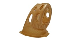
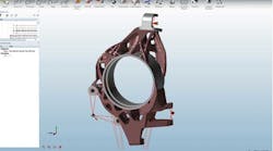
The bogey chassis connects the harrow device to the axle to enable the device to be transported from the farm to the field. Originally a welded structure weighing 245 kg, and with welding seam running 16.5 m long, it was a very complex and production-intensive design. To reduce manufacturing costs and make the structure lighter and more stable, Amazone decided to replace the bogey chassis. Using Altair’s Inspire “topology optimization software,” Amazone developers redesigned it as a casting, optimize the structural design for the operational needs of the component and for production efficiency.
Because the distribution of the material in the component can be optimized for the force (i.e., ground engagement) requirements, the cast bogey chassis is more than 45 kg lighter than the welded structure. At the same time, the new design is estimated to achieve 272% longer service life than the previous design, because the new casting has more uniform rigidity than the weldment.
As for the casting design process, Altair engineers simulated metal flow to identify and reduce the risk of internal defects cause by gas pockets during mold filling. And on that point, Amazone’s Sebastian Kluge noted: “The creation of the sand casting mold using 3D printing makes it possible to quickly source prototype components, and therefore significantly reduce development times.”
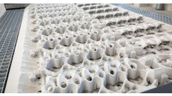
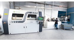
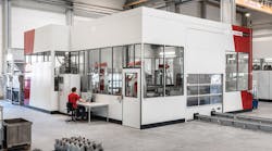
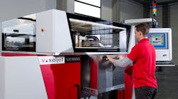
In general, manufacturing sand molds for such a complex component is time-consuming. Altair opted to print the bonded sand into the complex shape using the voxeljet VX4000 3D printing system, with a build space of 4,000 x 2,000 x 1,000 mm.
“This is the largest industrial 3D printer in the world for sand casting molds,” according to Tobias King, director marketing & application at voxeljet. “Because the complexity of the component does not affect the cost of the 3D printing, even difficult geometric shapes can be created at a low cost.”
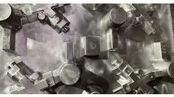
First, voxeljet converted the CAD file of the component into a negative CAD file to digitally represent the four-part sand mold. The data representing this new iteration of the design was installed into the 3D system, and then the printing began.
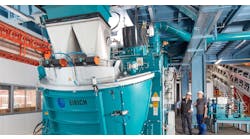
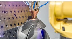
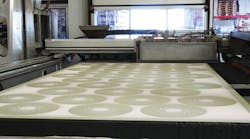
A “coater" spreads the printing medium (quartz sand) onto the build platform. Then, the print head moves about the platform depositing the grains in the CAD-defined pattern, and binding the layers of sand together with a bonding agent. The print head works with a resolution of 300 dpi — comparable in precision to high-resolution photography. While the build platform remains static, the coater and print head move about in the space and gradually upward by 300 micrometers per layer until the casting mold is complete.
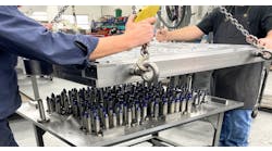
Once printing is finished, workers remove the side walls of the construction platform that were printed with the component and remove any misprinted quartz sand. This leaves the casting mold, which can be used right away.
At the Pro Cast Guss in Gütersloh, Germany, the mold is given a sealing coat as a barrier layer between sand and molten metal, to protect the mold from thermal stress. Nevertheless, like all sand molds it has a short useful life, but the casting simulation that preceded the final mold design ensures the success of the cast.
The rest of the story is a familiar one to metalcasters: they begin again, forming a new mold, initiating a new pour, and so on. The success is in harnessing all of the emerging and ongoing technology trends to identify a new and valuable product iteration, optimize a casting design, shorten the project development time, and ensure reliability of the cost and resources devoted to producing it.
