Latest from Melt/Pour
Optimizing your melt system to reach the lowest possible kilowatts (kW) and kVA of demand as part of your overall energy management program is critical to competitiveness in an industry where energy costs are a constant concern. The importance of melt-shop power supply utilization, efficiency and performance, and how it impacts power demand should be examined carefully. It directly influences the connected kW or kVA of demand for a given production rate. By increasing your melt shop power utilization rate you will increase and maximize the volume of metal poured per kW and kVA of demand. There are various ways that you can review these factors within your own foundry to find additional opportunities for conserving melt shop energy demand and usage.
By examining a typical melt shop and its energy usage we will find that melting represents the highest percentage of energy consumption in the foundry. Melting typically represents over 50% of the overall melt shop energy usage. Therefore, it offers the best opportunity for energy demand and usage cost reduction.
There are many critical factors influencing production versus demand, including efficiency, melt system performance, power supply technology and power utilization. The factors that are specifically part of power utilization include equipment type and configuration, operating practices, melt preparation, and the charging and pouring processes.
Efficiency First
Efficiency is a primary concern. Today’s induction power supplies provide substantially higher efficiency rates than earlier solid-state or hard-state technologies. These solid-state power supplies are achieving up to 98% efficiency. Foundries should review the efficiency of their existing melt system and evaluate the potential gains of using newer technologies.
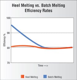
When reviewing efficiency, “batch” melting versus “heel” melting should be taken into consideration (see Figure 1). “Batch” melting is typically 7% more efficient than “heel” melting. This is a result of higher coil efficiency during the early stages of the batch melt cycle. As an example, looking at iron melting 7% can equate to as much as 30 kW hours for every ton melted. 30 kW hours over one year of production results in a substantial amount of additional energy usage and energy cost.
Melt Shop Performance — In order to maximize the achievable production for paid demand, it is important that your melt system has the ability to pull full power throughout the entire melt cycle. Today’s true batch melting systems should be designed to pull full power from the very beginning of the melt cycle, with the initial charge throughout the end of the melt cycle until the target temperature is reached. Some current and older technologies may not be able to reach full power during the early stage of the melt. As a result, you will not take advantage of the total demand you are paying for.
Power Supply Technology — Another part of performance associated with power supply technology is unit kW output versus the line kVA. Not all power supply technologies will lend themselves equally to demand control. When comparing current-fed and voltage-fed inverter technology, one technology maintains a consistent high line power factor at all power levels, whereas the other technology operates at a lower line power factor at reduced power levels. This also means that at reduced power levels, input kVA will be higher compared to those that run a consistent high power factor. These systems may not get the full benefit of demand control due to higher line kVA and/or power factor penalties at reduced power levels.
Power Utilization — Power supply utilization is the ratio of the melt time to the total melt cycle time. The total melt cycle time is made up of the melt time as well as the time required for tasks, such as temperature measurements, slag removal, chemistry analysis, pouring and initial recharging of the furnace. We also refer to this as the “off time” or “hold time” portion of the melt cycle.
For example, consider a melt shop with a melt time of 40 minutes. The time required for the “off time” functions is 22 minutes, therefore overall melt cycle time is 62 minutes. As a result, power supply utilization is 65%. In another example, where the melt time is 60 minutes and the “off time” is only 14 minutes, overall melt cycle time is 74 minutes, representing a power supply utilization of 81%. Both examples illustrate how being more efficient with “off time” functions can increase the utilization of a melt system power supply.
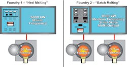
To illustrate that maximizing efficiency, melt system performance and utilization will achieve the highest production per kW or kVA of demand — it is best to compare the hourly pour rate versus the required power demand for two different melt systems, both producing 6 to 7 tons per hour, both with varying power demands (see Figure 2).
Foundry 1 is a one on one, mains frequency “heel” melting operation, with a demand of 5,000 kW and melt rate of 10 tons per hour. With a power utilization of 65%, the pour rate is 6.5 tons per hour. The power density is 250 kW per ton, which is typical for a mains frequency system.
Foundry 2 is a medium frequency “batch” melting system, which is already 7% more efficient than heel melting. This allows a further reduction of the kW or KVA demand while maintaining basically the same production. The higher efficiency combined with the higher utilization offered by the multiple-output power system results in a demand of only 3,000 kW.
Again, medium frequency makes it possible to increase the power density and reduce the size of the furnaces. This is a batch butterfly operation, wherein one furnace is melting while the other is either off or at hold for melt preparation and pouring. Once one furnace has completed its melt cycle the melting process begins on the second furnace, resulting in very high power supply utilization of 95%. Compared to Foundry 1, we have reduced the kW demand substantially while still maintaining a similar pour rate.
Figure 3 shows a comparison of data collected from both the “heel” and “batch” melting foundry examples. Note that although both were producing between 6 and 7 tons per hour, Foundry 1 has substantially higher kW demand (40% more) versus Foundry 2. This is a result of the power supply utilization, efficiency and performance. As the power supply utilization increases, the kW demand required for the same production volume decreases.
Figure 3 also shows how this could affect the total demand cost during a given month. For example, using $10 per month per kW of demand, Foundry 1 would have a demand cost of $50,000 versus Foundry 2 with a demand cost of only $30,000. That’s a difference of $20,000 a month or $240,000 over a year’s time.
Looking at this on a demand cost-per-ton basis, Foundry 1 paid $22.89 per ton while Foundry 2 paid $14.83 per ton. It’s clear Foundry 2 would have a substantial competitive advantage over Foundry 1, as a result of the latter’s use of older or less efficient technology.
Additional Opportunities to Conserve Energy Use
There are other areas that can be considered to reduce kW and kVA of demand and optimize your operation, including: the energy management system and how it interfaces directly with melt system controls; the melt system configuration; the use of automated controls available with today’s melt systems; automated furnace operations (e.g., slag removal, temperature sampling, chemistry analysis, and alloy adjustments); efficient scrap charging systems; and finally pouring and metal transferring practices. All of these can help to increase the utilization of your melt system.
Other ways to conserve demand energy usage include routine maintenance, maintaining your power transmission systems (which may include maintaining clean and secure terminations and connections), and properly configuring the furnace power leads. Proper use of furnace covers, meaning keeping the lid closed when possible throughout the melt cycle, to conserve radiant heat loss, is another recommendation.
Using cleaner scrap will reduce energy consumption. Anything that goes into the furnace will absorb energy, and impurities like dust, dirt, rust and slag take energy to melt, thereby increasing the kwh/ton for melting.
Don’t over charge or overflow the furnace. Furnaces are most efficient when operated at their design capacity. This will also make it easier to keep the lid closed.
Maintain the furnace lining dimensions according to the OEM specifications. In many cases linings have been thickened in order to increase lining life, but taking this step may decouple the furnace, resulting in decreased melting efficiency.
Ensure effective fume collection. Make sure the fume collection system is effective without unnecessarily robbing the furnace of energy and increasing thermal heat loss.
Finally, consider heat recovery systems for your melt shop. Many foundries today use heat recovery systems to return energy to the foundry, such as air handlers to recover warm air, or water-to-water heat exchangers to heat water in other areas of the foundry. These are just a few standard examples.
In conclusion, the melt shop is the largest area of energy consumption in a foundry, so it will offer the best opportunity for energy and demand cost reduction. Optimizing melt equipment utilization will minimize kW and kVA demand and maximize tons poured. Proper maintenance and operation of the melt system will reduce energy usage. New induction melting technology will increase performance, raise efficiency and enhance flexibility to achieve higher power utilization and lower costs of operation.
Michael Nutt is a District Manager with Inductotherm Corp. Visit www.inductotherm.com or email [email protected].
