During the past 50 years there has been a significant transformation in pouring technologies for metalcasting operations around the world, an evolution from manual (hand) pouring via semi-automated systems to completely automated systems. Although hand and semi-automatic pouring are still common today, high-volume foundries using bottom-pouring technology (featuring a stopper rods and nozzles) has embraced systems featuring closed-loop control, using metal level feedback from the pour cup to control the pour.
In the 1980’s, two technologies for providing this level feedback were introduced: vision cameras and laser systems. Since then, several hundred such bottom-pouring systems have been installed worldwide.
In 2004, pourTECH Group introduced the 3D Laser System, combining the best of laser and vision technologies. It provides the most reliable real-time level data in the industry. Ten years later, the System was improved by transitioning from a green to a blue line
laser, allowing more separation between the laser light and the illumination from the iron.
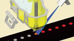
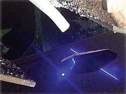
The 3D Laser System uses a line laser together with a custom camera. The line laser is placed on one side of the pour cup, aimed to project a blue laser line across the cup. On the opposite side, the 3D sensor picks up the image of the line, as it reflects in the metal surface. The sensor views the cup at an angle, and can determine the metal level in the cup by reading the position of the line.
For vertically parted molding lines, the traditional spot laser systems require a modification of the pour cup to provide an area for the laser to "see" the metal level while still keeping the cup size small. But, because the 3D Laser projects a line across the entire cup the camera is able to collect level data from both sides of the pour stream to provide more accurate information to the pourTECH™ control system, allowing it to optimize its pouring control decisions without the addition of the special laser area.
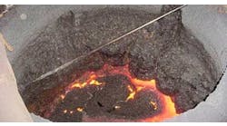
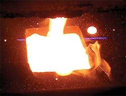
A traditional, vision-based pouring system depends on the illumination from the iron in the pour cup to make a level interpretation. The light contribution from the iron stream must however be discarded (because it doesn’t represent level), a sometimes difficult task as the iron stream can wander from side to side during the pour, or fan out if the nozzle condition deteriorates.
With its blue light source, the 3D Laser System is completely insensitive to the light from the iron (thanks to the difference in wave length) and because the line laser and 3D camera are on opposite sides of the iron stream, the sensor will see a break in the laser line where the stream enters the cup, making it possible for the sensor to ignore that part of the reading. This makes the 3D Laser System insensitive to variations in the iron stream (side-to-side movement and fanning of the stream). As long as the 3D Sensor can see a small portion of the line, the system can continue to operate – even with severely fanning iron streams.
In addition to the 3D camera, the device opposite the line laser houses a traditional point laser that is used to position the pouring vessel over the mold on vertical molding lines, or to perform a cup check on flask lines, verifying the flask has both sand and a cup before pouring starts. While a traditional vision system often requires additional equipment and mold features to locate the cup (lights and mold notches, as it is difficult to see a black hole in black sand), the 3D lasers point laser uses a combination of an active light source and simple triangulation to locate the cup.
The 3D Laser System is designed for use with small pour cups and does not require any cup modifications. Initially designed for pouring furnaces, the system has been adapted successfully for use with heated and unheated pouring ladles. PourTECH Systems with 3D lasers can be used together in pairs, for simultaneous pouring of two molds without any interference between the two systems.
The level data from the 3D Laser is further processed by the pourTECH system controller, which in turn controls the position of the actuator – and the opening of the stopper rod. This unit features an electric servo drive unit that moves at speeds of more than 100 mm/sec.
The pourTECH controller is designed to handle multiple external sensors, such as pyrometers and final level sensors, to provide foundry operators with additional production data.
With its Mold-Mapping feature, pourTECH will track each mold as it moves down the cooling line and allows the operators to view critical data (e.g., pouring status, iron temperature, and final level) on the operator’s panel. The data displayed on the screen can be augmented with batch numbers, lab analyses, and other pattern and pour specific information. The collected data can be sent to an external database, where it can be kept as a quality record for each pour, fully accessible by the plant engineers. With mold mapping, it is possible to provide Cooling Time Control (CTC), to ensure that each mold is sufficiently cooled before it leaves the cooling line, while optimizing the production rate for the highest possible mold rate, taking advantage of line stoppages due to breakdowns, pattern changes, etc to keep the mold rate up.
Providing accurate level feedback is critical for controlling the pour in an automatic system. By using a combination of laser and vision, the 3D Laser System gives the best of both worlds.
Goran Lowback is the president of Viking Technologies Inc. Visit www.vikingtechnology.com.
