Latest from Testing/QC
There are two primary methods used to verify the internal soundness of steel castings that are governed by ASTM standards. One is ultrasonic inspection, which uses a transducer and diagnostic machine to send and receive an ultrasound waveform. The reflection or pulse-echo will be returned either from the back wall of the casting or from any imperfection or cavity within the wall. The second technique is radiography — which uses X-rays and gamma rays.
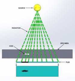
The radiography process — In this process, X-rays produced by a generator are projected toward an object. Some of the X-rays are absorbed by the object while others pass through and are captured on the far side of the object by photographic film or digital detectors. Visual inspection of those resulting images will reveal internal flaws, and these flaws can be graded against ASTM standards.
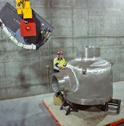
In film radiography the source of radiation is placed on one side of the object to be radiographed and the film on the opposite side. A grid pattern using lead location or station markers is established on the part to allow for coordination of the film to the area of the part being radiographed. Image quality indicators (penetrameters) also are placed on the source side of the object to ensure the technique parameters are valid. The gamma or X-rays pass through the object and expose the film.
The formation of an image on the film depends upon the amount of radiation received by different areas of the film. As lead is denser than steel, the areas where the location or station markers are positioned will absorb more of the gamma or X-rays than the surrounding steel base material. This will cause the image of these markers to show as “minus density” (lighter) images on the film. If the material has non-metallic inclusions, such as sand, slag, gas porosity, or shrinkage, these areas are less dense than the surrounding sound material.
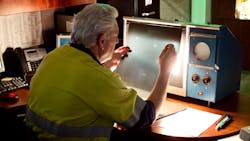
Consequently, more gamma or X-rays will be transmitted through these areas and the exposure of the film is greater there. The result is “plus density” (darker) images in the flawed areas on the film. When these flawed areas appear on the exposed film they are evaluated by comparing them with ASTM Standard reference radiographs for acceptability, using the steel casting industry’s three primary sets of reference radiographs based on material thickness. Each of these standard sets of reference radiographs contains six categories of graded discontinuities found in castings, in increasing severities from 1 (best) to 5 (worst), and four categories of ungraded discontinuities, furnished as examples only. The flawed areas on the film are first categorized according to the type of discontinuity (gas, sand, slag, shrinkage, etc.), and then evaluated for severity from 1 to 5.
Bradken manufactures differentiated consumable and capital products for mining, construction, rail and transit, energy, and general industrial markets. The company operates at 59 manufacturing, sales and service sites worldwide, and posts sales revenue of more than $1.4 billion.
Bradken is organized as four divisions and six business units for specific markets. The Energy Business draws from all of the Bradken operations, and operates three steel foundries and two machine shops in North America (Tacoma and Chehalis, WA and London, ON.) These operations offer engineering, patternmaking, casting, machining, fabricating, and non-destructive testing services. Certifications include ASME, ASNT, HAF 604 (China Nuclear), MIL-STD, PED and NORSOK.
Bradken’s Tacoma, WA, steel foundry has been in continuous operation since 1899, and while radiographic inspection technology has been used in industrial inspection for decades, the foundry has been using radiography for non-destructive inspection of its cast products since 1978. At that time, an 8-MeV (million electron Volts) linear accelerator was installed, capable of radiographing sections up to 17 inches thick. Since then, radiographic inspection of mission-critical cast pumps and valves used for nuclear power generation, offshore drilling operations, and military applications, has increased steadily.
With increasing demand for such products — for example, Bradken has experienced a 40% increase in demand for radiography of pump castings — the rate of inspection started to rise dramatically in 2010. Catastrophic system failures at the Fukushima nuclear power plant in Japan, and Deepwater Horizon offshore rig in the Gulf of Mexico have caused many industries to review their exposure to such risks, and to recognize the danger and liability of product failures. These events have led to a significant increase in demand by casting buyers for radiographic inspection.
Addressing the Issue
Initially Bradken turned to subcontractors to handle customers’ increased demand for radiography, but the rate of the increase in demand coupled with supplier constraints in lifting weight limits, size, and film processing quality, demanded a better solution. A proposal was put together to add additional radiographic capacity in the form of a second concrete bunker with a new, higher-powered 9-MeV linear accelerator that would expand Bradken’s radiographic capacity and capability. The project was approved in July 2011, and the design for the new vault and building was started.
To ensure the new construction would meet state and NRC requirements, Bradken hired a Washington State Department of Health-approved physicist to review and comment on the project engineering. The building design and materials went through several revisions before they were approved, and the final building included a vault with 8.0×40.0-ft-high walls and an 18-in.-thick concrete roof.
After construction was complete, two radiographic systems were installed: a 9-MeV linear accelerator supplied by Varian Medical Systems’ Security and Inspection Products, and a Cobalt 60 projector and source supplied by QSA Global.
AeroGo provided a 50-ton-capacity custom turntable for positioning and manipulating the steel castings during the inspection process, and a 50-ton crane was installed, too.
After commissioning the new equipment, a full environmental radiation survey of the building and surrounding area was performed to confirm that the approved shielding plan was indeed adequate. The survey was completed and the facility met all of the shielding requirements. Also, the survey was filed with the Washington State Dept. of Health, as a matter of record. The new radiographic facility, the second for Bradken at Tacoma, was approved for use in 2012.
Demand Continues to Rise — The second inspection facility was designed to match the current and forecasted demand for Bradken’s production processes. The new inspection systems, combined with the existing resources, allow Bradken to offer its global customer base sufficient capacity and valuable capabilities, including:
• 1×8-MeV linear accelerator for castings up to 17 in. (430 mm) thick;
• 1×9-MeV linear accelerator for castings up to 20 in. (510 mm) thick;
• 1×249-curies Cobalt 60 radioactive source for castings up to 8 in. (200 mm) thick;
• 1×100-curies Cobalt 60 radioactive source for castings up to 8 thick (200 mm) thick; and,
• 1×100-curies Iridium 192 radioactive source for castings walls up to 3” thick (75 mm.)
Castings up to 14×14×14-ft. (4.3× 4.3×4.3 m) and weighing up to 50 long tons (50,800 kg) can be processed in this new inspection center, across a broad range of steel alloys that includes Inconel, stainless, carbon and low alloy. Sixteen radiographers and three film readers staff the facilities across three shifts. Radiographers are qualified to SNT-TC-1A Level II and III. The staff also includes MIL-STD-2132 and NAVSEA 250-1500-1 test examiners.
Currently all film is processed through automatic processors. Eventually, much of this activity will be switched to digital processing, as the technology evolves and improves to handle heavy-section image quality.
Since the completion of the new radiographic center, demand for casting inspection has continued to increase. Bradken continues radiographic inspections across three shifts to keep up with the demand, and customers’ responses have confirmed the validity of the decision to invest in additional radiographic capacity (see sidebar.)
The internal examination of castings by radiography will reveal internal flaws, so as the demand for radiographic examination increases the available upgrade capacity and capability also must increase.
To address this need Bradken developed extensive welder training programs to elevate the skills of commercial welders, and doubled its radiographic-quality welding capacity. Technical support for casting design was enhanced, too, by adding a state-of-the-art cluster computer network. A MagmaSoft simulation and optimization system is available to run multiple, rapid simulations on casting solidification and stress, developing optimized designs quickly and at the least possible cost.
Stan Truselo is the QA Manager for Bradken Energy’s metalcasting operation in Tacoma, WA. Contact at him at [email protected]
